Insert for an opening of an appliance

a technology for inserting sockets and openings, which is applied in the direction of sleeve/socket joints, electrical appliances, couplings, etc., can solve the problem that the housing socket mounted on the wall area of an appliance can come loos

Active Publication Date: 2009-07-21
LAPP ENG
View PDF19 Cites 34 Cited by
  • Summary
  • Abstract
  • Description
  • Claims
  • Application Information

AI Technical Summary

Benefits of technology

[0006]The advantage of the solution according to the invention is to be seen in the fact that with a pressure ring designed in such a manner it is possible, in a simple manner, to secure the housing socket on the wall area having the opening in a stable manner.
[0057]Another advantageous solution provides for the pressure ring to have recesses corresponding to the size and the arrangement of the snap elements. These recesses allow the pressure ring to move beyond the snap elements without any deflection movement thereof.

Problems solved by technology

The problem with these inserts is, however, that the housing socket mounted on the wall area of an appliance can come loose.

Method used


Image

  • Insert for an opening of an appliance
  • Insert for an opening of an appliance
  • Insert for an opening of an appliance

Examples


first embodiment

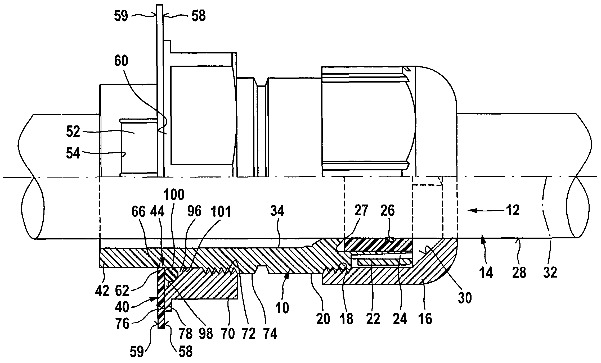
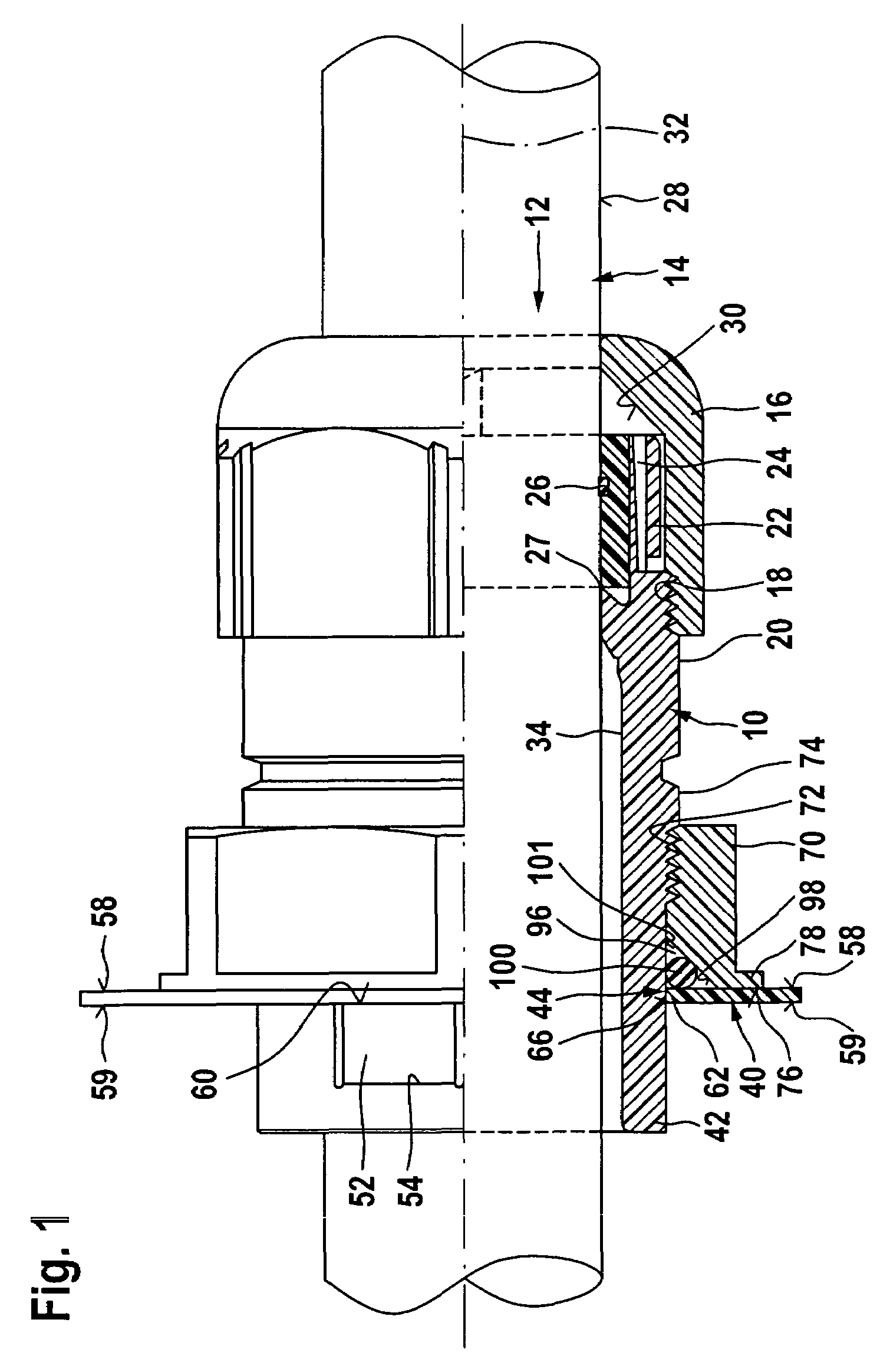
[0092]On the contrary, in the first embodiment it is possible to attach the pressure ring 70 only from the side of the assembly section 42, wherein the internal thread 72 must be moved beyond the snap elements 46 which is, however, possible due to the fact that the tongues 52 can deflect in an elastic manner with their supporting surfaces 60 radially inwards towards the central axis 32.

[0093]As a result of the fact that the thread 72, 74 provided for displacing the pressure ring 70 with the flange surface 76 in the direction of the wall area 40 is a left-hand thread, this will not come loose during tightening of the cap nut 16 with a right-hand thread but continue to tighten and so it is ensured that the cable feed-through once mounted on the wall area 40 by means of the assembly device does not come loose during the subsequent fixing of the cable 14 guided through the cable feed-through with the fixing member 12 due to tightening of the cap nut 16 but remains securely mounted on th...

third embodiment

[0105]In a cable feed-through according to the invention, illustrated in FIG. 5, only the housing socket 10 is likewise illustrated, with the pairs 92 and 94 as well as the pairs 102 and 104 of snap elements 46.

[0106]Moreover, the tongues 52 are provided in the area of their supporting surfaces 60 and their centering surfaces 64 with a coating 106 which increases friction at the edge 62 of the opening and improves the frictional securing of the assembly section 42 in the opening 44.

fourth embodiment

[0107]Alternatively to the provision of the coating 106, the tongues 52 of the pairs 92, 94, 102, 104 are provided in a fourth embodiment illustrated in FIG. 6, which likewise merely shows the housing socket 10, with ribs 108 which likewise have a friction-increasing effect in the area of the opening 44 by abutting on the edge 62 of the opening in order to improve the force-locking and non-rotatable fixing of the assembly section 42 to the wall area 40.

[0108]As for the rest, both the third and fourth embodiments are identical to the preceding embodiments and so reference is made to the explanations concerning these embodiments.

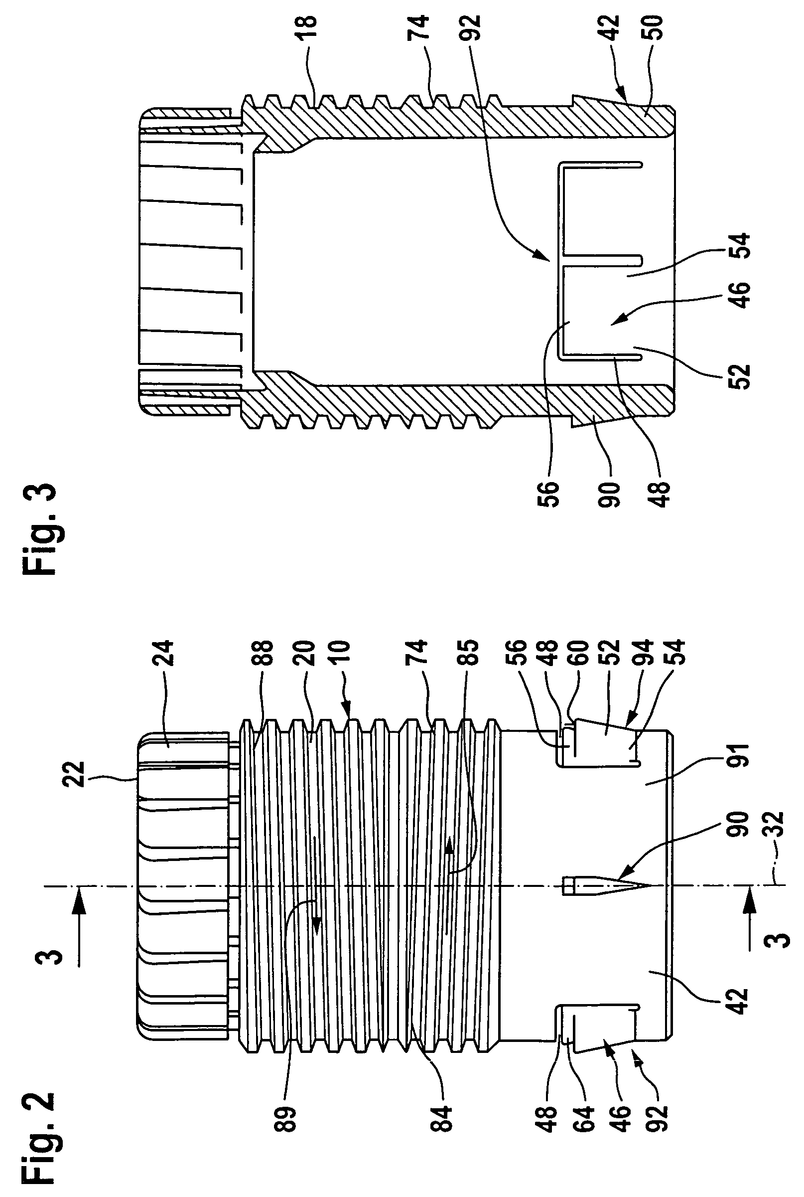
[0109]In a fifth embodiment, the pressure ring 70′ is preferably designed such that its internal thread 72 has recesses 110 and 112 which have in circumferential direction an angular extension corresponding to the pairs 92, 94 of tongues 52 and so the pressure ring 70′ can move over the tongues 52 of the pairs 92, 94 as in the first embodiment without the nece...


PUM


Abstract

In order to improve an insert for an opening in a wall area of an appliance comprising a housing socket, an assembly device provided on the housing socket, with an assembly section which can be guided through the opening in the wall area and has snap elements which engage behind an edge of the opening as well as with a pressure ring which is arranged on the housing socket at a distance from the snap elements and can be adjusted in the direction of the snap elements by means of an advancing guide as a result of a rotary movement about the central axis, in such a manner that a secure assembly of the housing socket is possible, it is suggested that the pressure ring be rotatable in a first direction of rotation in order to secure the housing socket and that the housing socket be adapted to be fixed against any co-rotation in the first direction of rotation by means of a holding section element.

Description

BACKGROUND OF THE INVENTION[0001]The invention relates to an insert for an opening in a wall area of an appliance, wherein the opening is provided, in particular, for feeding a cable through it, comprising a housing socket, an assembly device provided on the housing socket with an assembly section which can be guided through the opening in the wall area of the appliance and has snap elements which engage behind an edge of the opening as well as with a pressure ring which is arranged on the housing socket at a distance from the snap elements and can be adjusted in the direction of the snap elements by means of a first advancing guide as a result of a rotary movement about the central axis.[0002]Inserts of this type designed as cable feed-throughs are known from DE 41 28 632 C1.[0003]The problem with these inserts is, however, that the housing socket mounted on the wall area of an appliance can come loose.[0004]The object underlying the invention is, therefore, to improve an insert of...

Claims


Application Information

Patent Timeline
Patent Type & Authority Patents(United States)
IPC IPC(8): H02G3/18
CPCH02G15/007H02G3/0675Y10T403/60H02G3/0691
Inventor DROTLEFF, ROLFZANKL, MARTINMUELLER, DANIELMIKELER, EUGEN
Owner LAPP ENG
Why Eureka
Try Eureka