
Fitted covering having diagonal elastic bands

a technology of elastic bands and fitted sheets, which is applied in the field of fitted coverings, can solve the problems of significant forces applied to the diagonal bands at the corners of such sheets, the construction of fitted sheets described in the '403 patent may be economically prohibitive to manufacture, and the effect of tight corners and easy placement on the mattress

Active Publication Date: 2009-07-28
HOMTEX
View PDF30 Cites 8 Cited by
  • Summary
  • Abstract
  • Description
  • Claims
  • Application Information

AI Technical Summary

Benefits of technology

The solution enhances the durability and attachment strength of elastic bands, preventing detachment during abnormal use, while reducing material usage and ensuring a snug, wrinkle-free fit on mattresses, thus providing a more economical and ergonomic fitted sheet solution.

Problems solved by technology

Although the elastic binding and elastic bands provide adequate retention onto a mattress, one drawback of existing band designs is that when a sheet is grasped to lift up the underlying mattress, significant forces may be applied to the diagonal bands at the corners of such sheets.
Although the fitted sheet construction described in the '403 patent has adequate strength at the connection points of the diagonal elastic bands for most operations, in certain situations and during certain abnormal use, elastic band 50 may be yanked loose from the fitted sheet and thus tear the sheet at the connection point.
For certain manufacturing requirements, the fitted sheet construction described in the '403 patent may be economically prohibitive to manufacture.
Additionally, for certain fit and finish requirements, the fitted sheet construction described in the '403 patent may have an insufficient wrinkle-free fit and finish.

Method used


Image

  • Fitted covering having diagonal elastic bands
  • Fitted covering having diagonal elastic bands
  • Fitted covering having diagonal elastic bands

Examples


first embodiment

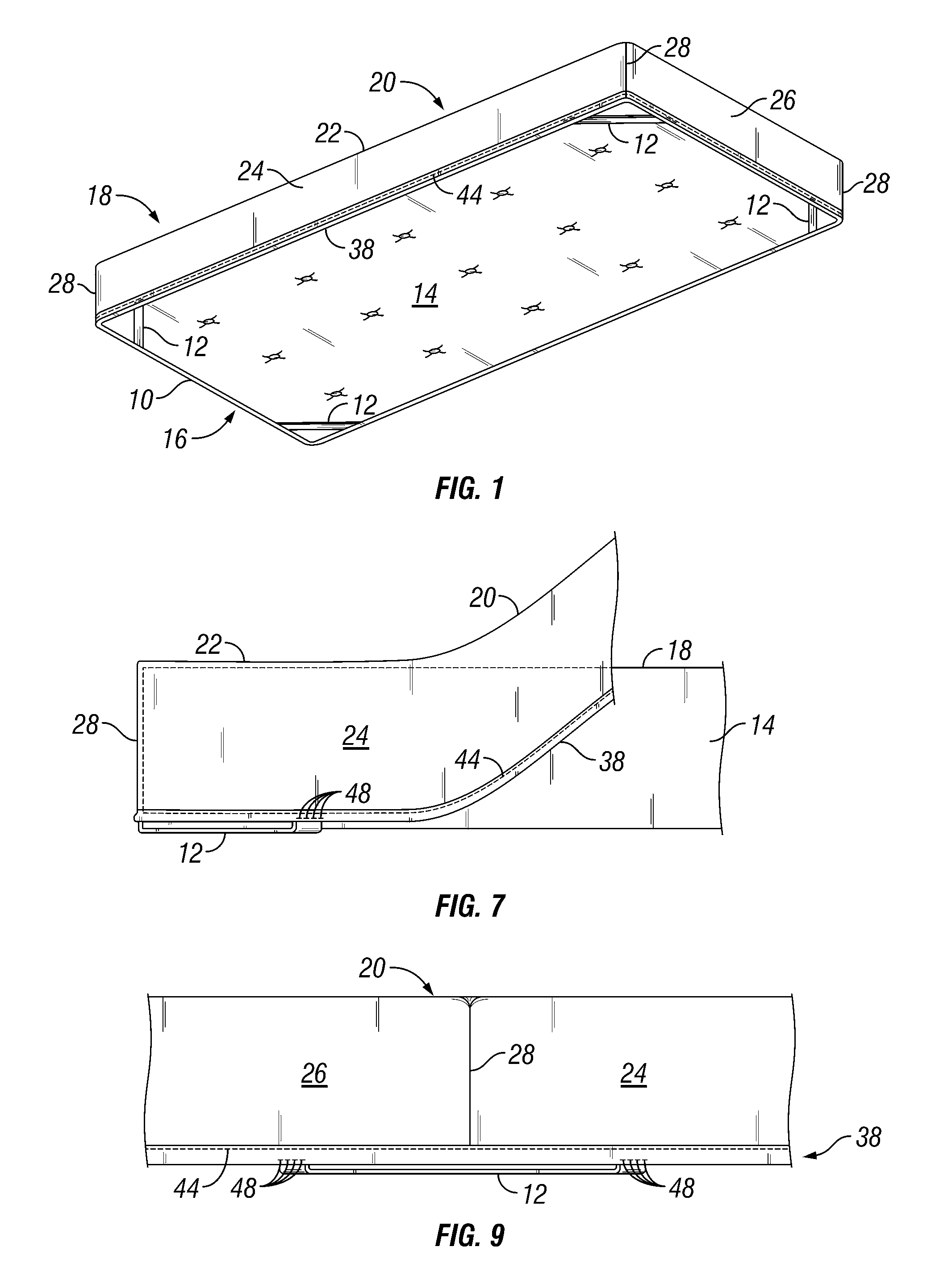
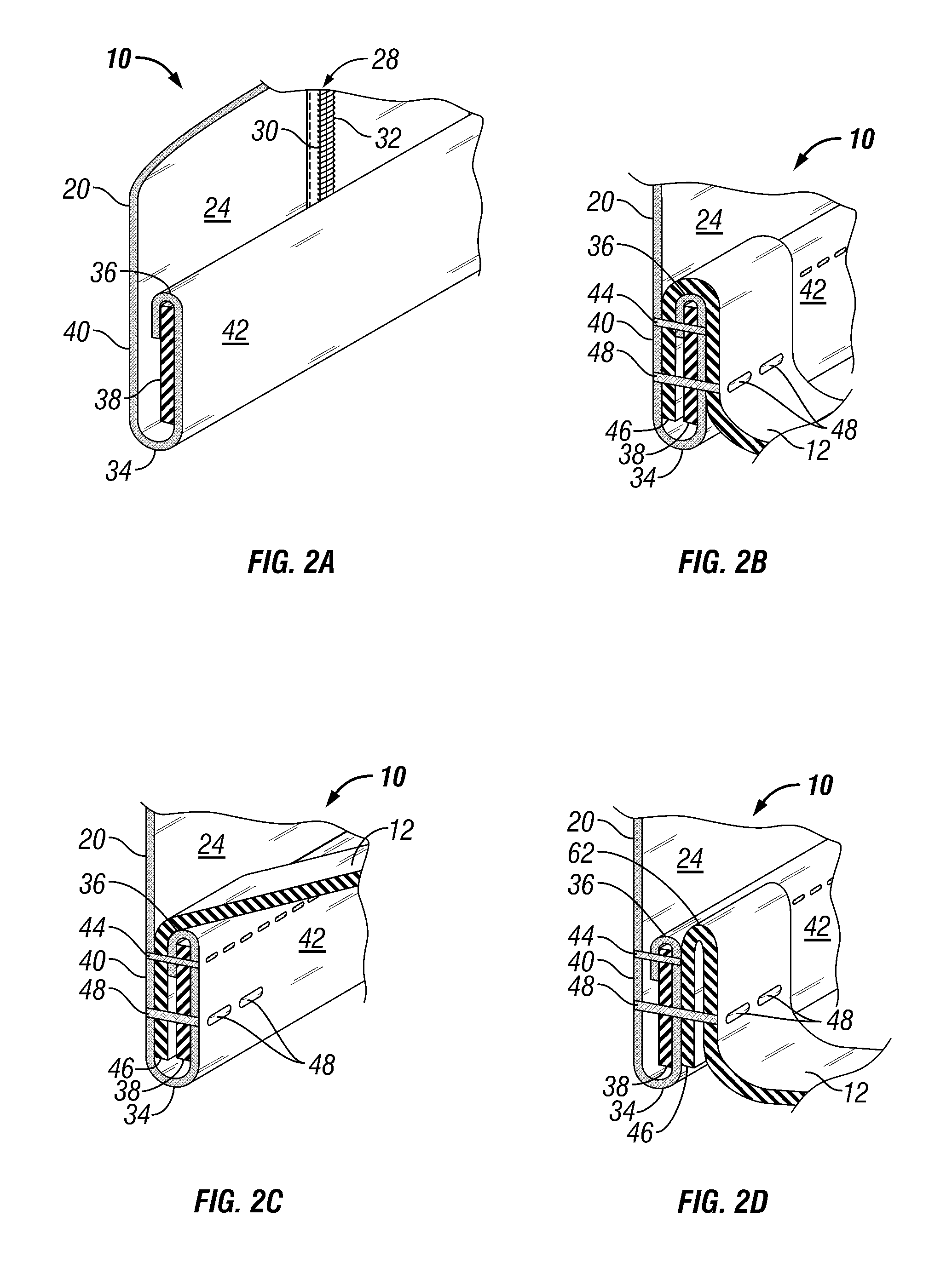
[0080]With reference to FIGS. 1, 2(a)-2(g) and 7-9, fitted covering 10 will now be described in detail.

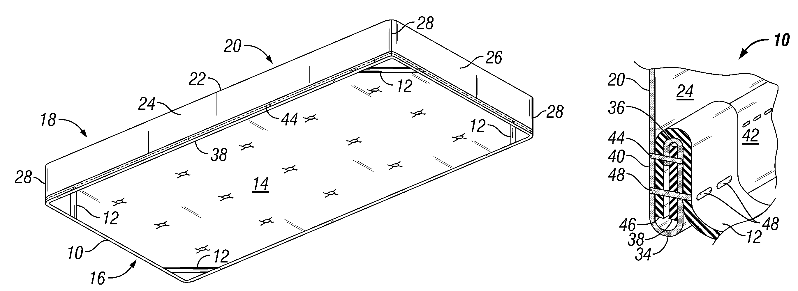
[0081]Specifically, as shown in FIG. 1, fitted covering 10 including a plurality of diagonal elastic bands 12 is illustrated as being mounted on a conventional rectangular mattress 14 having a bottom face 16 and an opposite upper face 18. Fitted covering 10 generally comprises a body 20 formed of any suitable fabric such as cotton, a cotton blend or satin and the like. Body 20 may include a top portion 22, opposite side portions 24 and opposite end portions 26. Adjacent side and end portions may be seamed together in the usual manner at four seams to form four vertical corners 28. As seen in FIG. 2(a), each seam defining a vertical corner may include a straight line of stitching 30 and a conventional overlock, safety stitch 32 or other seam securing methods. The same may be applicable to the horizontal corners (not shown) of covering 10. Alternatively, a variety of other horizontal...

second embodiment

[0101]With reference to FIGS. 1, 3(a)-3(g) and 7-9, fitted covering 100 will now be described in detail.

[0102]Specifically, referring to FIG. 1, with elements such as body 20, top portion 22, opposite side portions 24, opposite end portions 26, vertical corners 28, stitching 30 and overlook or safety stitch 32 being similar to those described above for the first embodiment of fitted covering 10, as shown in FIG. 3(a), each side portion 24, and likewise each end portion 26, may include a bottom section 34 terminating generally at end 35. As discussed above, a variety of other horizontal or vertical corner formation methods known in the art may be used, and for the fitted covering described herein, instead of vertical or horizontal corners, fitted covering 10 may be of the “cornerless” variety, wherein a single or plural layers of fabric may form the cornerless fitted covering. For the embodiment of FIG. 3(a), a cloth binding 37 may be folded over in a mirror-image inverted J-shaped c...

third embodiment

[0121]With reference to FIGS. 1, 4(a)-4(g) and 7-9, fitted covering 200 will now be described in detail.

[0122]Specifically, referring to FIG. 1, with elements such as body 20, top portion 22, opposite side portions 24, opposite end portions 26, vertical corners 28, stitching 30 and overlook or safety stitch 32 being similar to those described above for the first embodiment of fitted covering 10, as shown in FIG. 4(a), each side portion 24, and likewise each end portion 26, may include a bottom section 34 folded over in an inverted U-shaped configuration so as to form a reinforced double fabric layers 52 for securing of elastic binding 38 and elastic band 12. As discussed above, a variety of other horizontal or vertical corner formation methods known in the art may be used, and for the fitted covering described herein, instead of vertical or horizontal corners, fitted covering 10 may be of the “cornerless” variety, wherein a single or plural layers of fabric may form the cornerless f...


PUM


Abstract

A fitted mattress covering for a mattress includes lower edge portions, which may be inverted J-shaped portions, mirror-image inverted J-shaped portions, portions that terminate at an end, or inverted U-shaped portions. The covering side and end portion lower edges may join one another to form a continuous lower edge of the covering. For the J-shaped portion, an elastic binding may be disposed under a downwards folded portion. The elastic binding may extend at least partially along the length of the lower edge of the covering. An elastic band may be disposed at each corner of the covering and extend diagonally across the associated corner and have opposite ends secured adjacent one of the side portions and adjacent one of the adjacent end portions, respectively. The bands may be secured in place by stitching and / or by supplementary securing means to ensure that the bands do not pull away from the covering.

Description

RELATED APPLICATION[0001]This application claims benefit of priority of U.S. application Ser. No. 10 / 992,677, filed Nov. 22, 2004, hereby incorporated by reference in its entirety.BACKGROUND OF INVENTION[0002]a. Field of Invention[0003]The invention relates generally to fitted coverings for mattresses, and, more particularly to an improved fitted covering having diagonally extending elastic bands at the corners thereof for holding the covering in place relative to the corners of the mattress.[0004]b. Description of Related Art[0005]In the art, there presently exist a variety of known fitted sheets for mattresses and the like. Such sheets typically employ an elastic binding at the lower edge of the sheets. For certain sheet designs, additional widthwise or diagonally extending elastic bands may be provided at the corners of the sheet. The elastic binding in conjunction with the elastic bands facilitates fitting of the sheet on mattresses of different sizes, and further eliminates wri...

Claims


Application Information

Patent Timeline
Patent Type & Authority Patents(United States)
IPC IPC(8): A47G9/04
CPCA47G9/0246
Inventor WOOTTEN, JR., GERALD E.
Owner HOMTEX
Learn More