Bi-directional mounting bracket assembly for exterior siding

a mounting bracket and exterior siding technology, applied in the field of bi-directional mounting bracket assembly, can solve the problems of siding being exposed to rain or water, exposing the sheathing to moisture, and a host of problems, so as to reduce or eliminate structural maintenance, improve water shedding capability, and eliminate or reduce the exposure of the sheathing

Inactive Publication Date: 2009-07-28
TAPCO INTERNATIONAL CORPORATON
View PDF49 Cites 36 Cited by
  • Summary
  • Abstract
  • Description
  • Claims
  • Application Information

AI Technical Summary

Benefits of technology

[0009]Features, advantages and benefits of the present invention include a mounting bracket assembly having an irregular or rectangular shape that can be selectively mounted in at least two positions without degrading the assemblies self-flashing and water shedding capability. Other advantages include improved water shedding capabilities that eliminates or reduces exposure of the sheathing to moisture that could cause damage to structural material and potentially attract unwanted insects. The assembly reduces or eliminates of structural maintenance, has a design that is relatively simple, robust and versatile, and is inexpensive to manufacture and easy to install.

Problems solved by technology

Unfortunately, the siding is typically exposed to rain or water which flows down the siding and beneath the exterior flange.
Accumulation of water directly against the mounting flange can cause water propagation outward from the wall of the base member and beyond the mounting flange, thus exposing the sheathing to moisture.
The retained moisture can potentially create a host of problems including the rot of wood, disintegration of simulated materials and the attraction of unwanted insects.
Unfortunately, known self-flashing bracket assemblies can be mounted in one position only.
This requires separate manufacturing molds / tooling and can complicate shipping and stocking of the product.

Method used


Image

  • Bi-directional mounting bracket assembly for exterior siding
  • Bi-directional mounting bracket assembly for exterior siding
  • Bi-directional mounting bracket assembly for exterior siding

Examples


Embodiment Construction

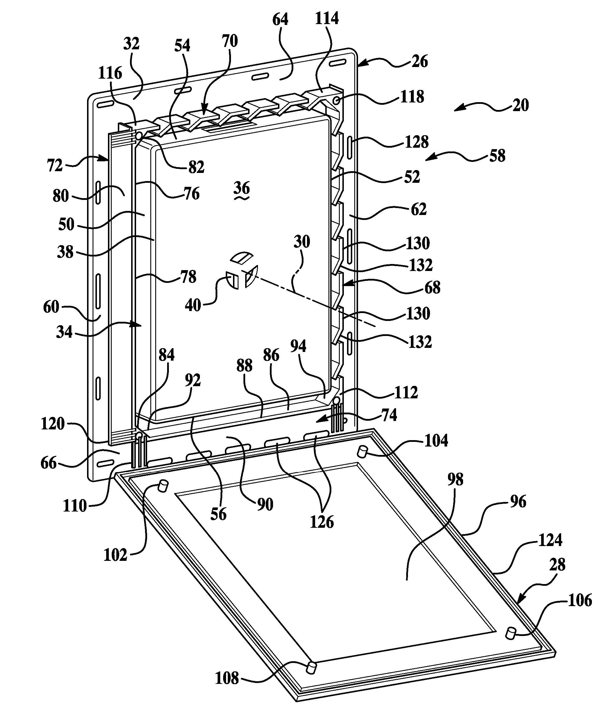
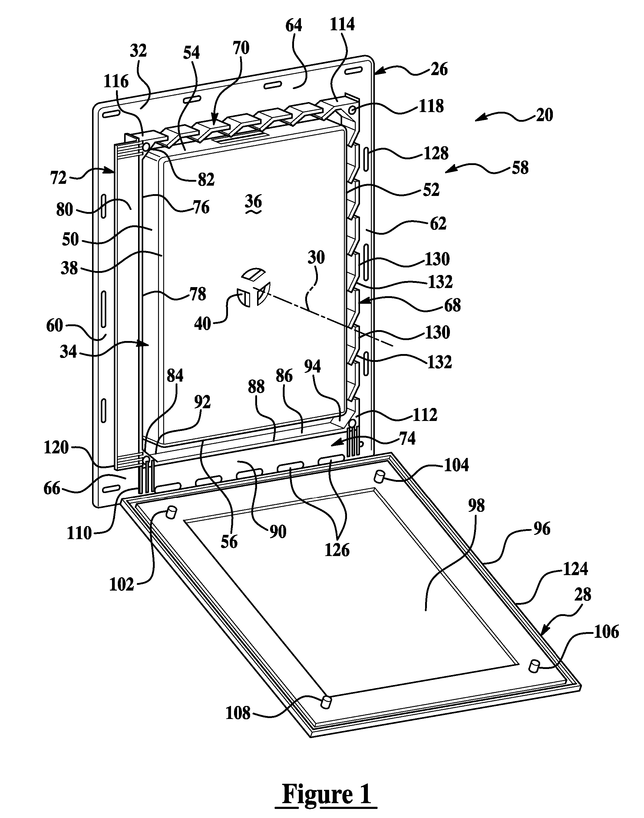
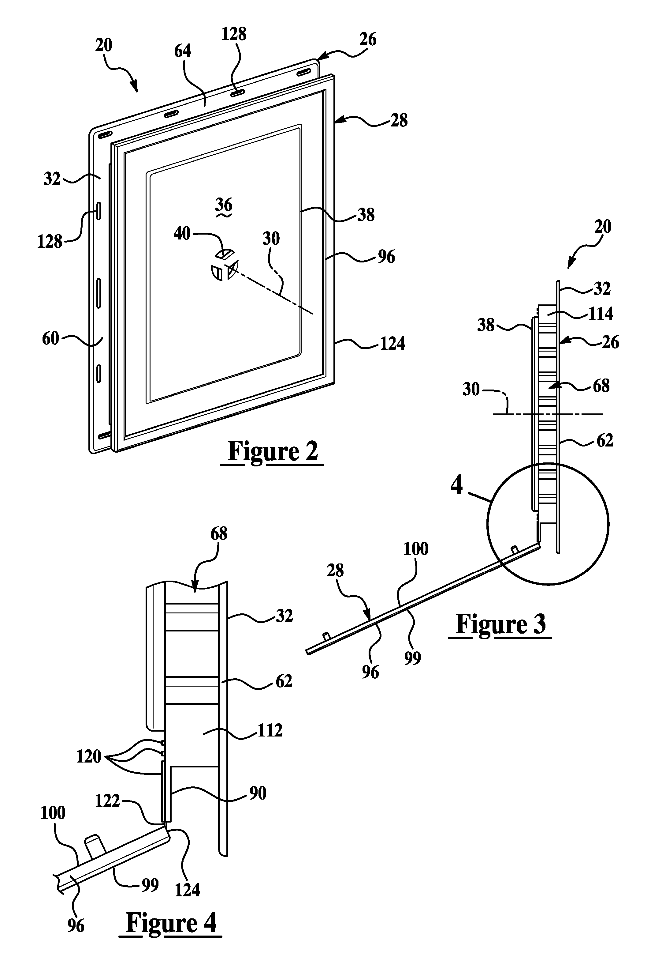
[0015]As best illustrated in FIGS. 1-4, a bi-directional mounting bracket assembly 20 embodying the present invention generally projects or is exposed through exterior siding (not shown) of a substantially vertical wall of any variety of buildings or residential structures exposed to inclement weather such as rain and generally water runoff. The assembly 20 provides an aesthetically pleasing surface for which any variety of exterior components can be easily mounted or project therefrom. Such components include but are not limited to hose spigots, electrical receptacles, clothes dryer vents, and light fixtures.

[0016]The assembly 20 is fastened to a substructure of the exterior wall preferably prior to placement of the siding. The substructure is generally an underlayment or sheathing that is preferably covered by the siding material. The mounting bracket assembly 20 is generally self-flashing for the prevention of water seepage beneath the siding, and has a base member 26 secured to ...


PUM


Abstract

An bi-directional mounting bracket assembly is utilized in conjunction with exterior siding that covers sheathing of an exterior wall. A base member of the assembly has a mounting flange secured to the sheathing and a wall arrangement that projects outward with respect to the sheathing and from the mounting flange. Preferably, the wall arrangement supports a raised central panel used for mounting of fixtures. The wall arrangement preferably has four walls extending laterally between the mounting flange and the central panel. Spaced radially outward from the two adjacent walls are respective first and second drip ledges, and spaced radially outward from the other two adjacent walls are respective first and second baffle sets. When the assembly is mounted to the sheathing, a selective one of the two drip ledges is disposed substantially horizontally and beneath the wall arrangement for shedding of water. The baffle set adjacent to the horizontal drip ledge cascades water downward and generally toward the respective wall to channel water upon the horizontal drip ledge.

Description

RELATED APPLICATIONS[0001]This patent application claims priority to and all advantages of U.S. Provisional Patent Application No. 60 / 712,523 which was filed on Aug. 31, 2005.FIELD OF THE INVENTION[0002]The subject invention generally relates to an exterior siding mounting bracket assembly and more particularly to a bi-directional mounting bracket assembly.BACKGROUND OF THE INVENTION[0003]Common in residential building structures, sheathing of an exterior wall is known to be covered with a siding material typically made of cedar, aluminum, plastic or other synthetic material often made to appear like wood. Often, various exterior appendages of the home such as cloths dryer vents, exterior light fixtures, electrical outlets, and water spigots must be trimmed-out around the siding for aesthetic reasons. This is commonly done with a mounting bracket. One such example of a known mounting bracket is taught in U.S. Pat. No. 4,920,708, assigned to the same assignee as the present invention...

Claims


Application Information

Patent Timeline
Patent Type & Authority Patents(United States)
IPC IPC(8): A47F5/08
CPCA47J17/02A47J23/00E04F19/00F24F13/084Y10T16/558F21V21/02Y10S248/906E04F19/02Y10T137/698
Inventor BONSHOR, DAVID JAMES
Owner TAPCO INTERNATIONAL CORPORATON
Why Eureka
Try Eureka