Endoscope optics with a lateral optic-fiber bundle

a fiber bundle and optic technology, applied in the field of endoscope optics, can solve the problems of less satisfactory illumination of the field of view, and achieve the effect of improving the quality of vision

Active Publication Date: 2009-08-04
OLYMPUS WINTER & IBE
View PDF18 Cites 3 Cited by
  • Summary
  • Abstract
  • Description
  • Claims
  • Application Information

AI Technical Summary

Benefits of technology

[0013]When, as regards the conventional design, the two tubes are axially offset from one another, the guide duct tapers downward. As a result fewer fibers are present in the lower guide duct zone and the illumination of the field of view is then less satisfactory. This drawback is eliminated by the features of the present invention. The fiber tube chamfer in the lower guide duct widens this duct and the centroid of the fibers is shifted downward. While the gap between the tubes is constricted proximally on account of the chamfer, no drawback is incurred thereby because the fibers are incoming obliquely from above from zones of larger cross-sectional area. The chamfer makes it possible to extend the fiber tube distally as far as possible at a large inner cross-sectional area required for the installation of the objective lens at that site.
[0014]With the present invention, the endoscope optics comprises two symmetrical, lateral bundle portions, thereby doubling the light output.
[0015]Other features of the invention are advantageous. To further increase the light output, a third bundle portion is used which is laterally bounded by the outer tube's internal protrusions which are present anyway. The compression required for the alignment into parallelism is carried out by an upper outer protrusion at the fiber tube.

Problems solved by technology

As a result fewer fibers are present in the lower guide duct zone and the illumination of the field of view is then less satisfactory.

Method used


Image

  • Endoscope optics with a lateral optic-fiber bundle
  • Endoscope optics with a lateral optic-fiber bundle
  • Endoscope optics with a lateral optic-fiber bundle

Examples


Embodiment Construction

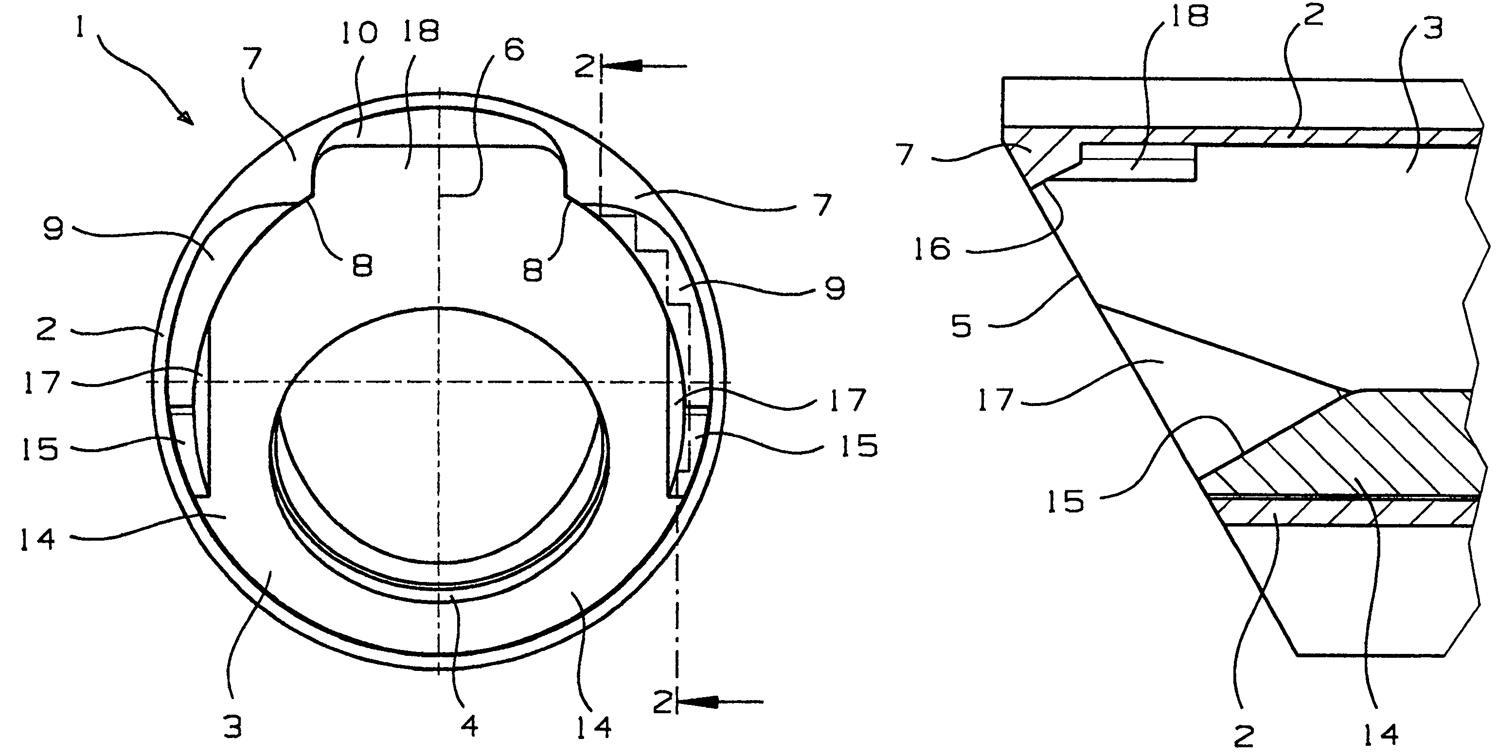
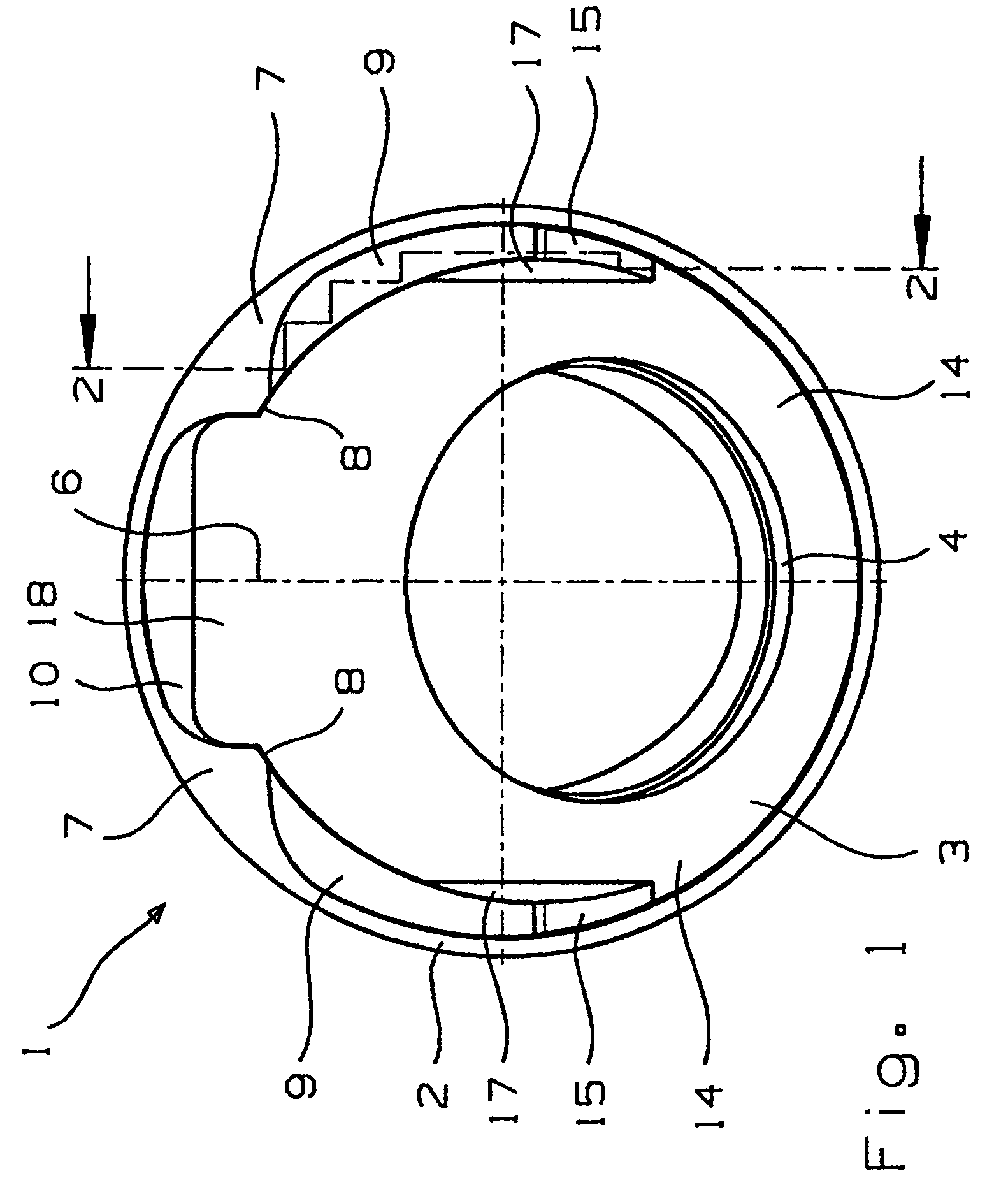
[0023]The comparatively complex geometry of the endoscope optics of the invention is shown by a preferred embodiment mode in FIGS. 1 through 5 which are different views of the same optics.

[0024]FIG. 1 is an axial front view of an endoscope optics 1 comprising a outer tube 2 and a fiber tube 3. FIG. 5 shows the outer tube being longitudinally thin-walled; the fiber tube 3 also is longitudinally thin walled but inwardly reinforced at its distal end zone in order to subtend an opening 4 receiving a round window. An omitted optics is mounted inside the fiber tube 3 and looks through the window. An image guide, for instance a configuration of relay lens elements or an optic fiber bundle, also omitted, is situated to the rear. Also a video camera may be mounted behind the objective lens.

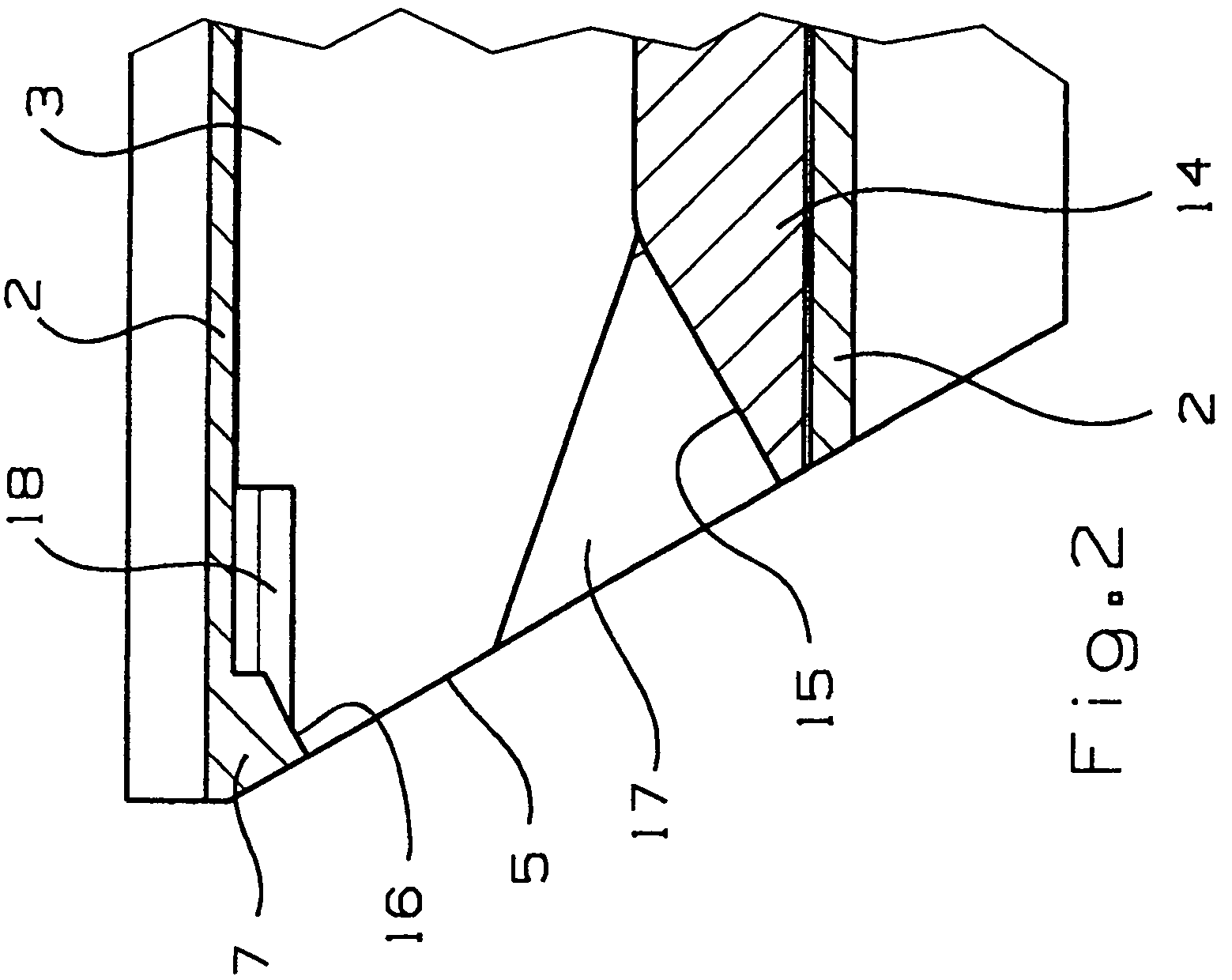
[0025]The sideview of FIG. 2 shows that the endoscope optics' end face 5 runs obliquely to the axis of the outer tube 2. The window aperture 4 is oriented in the plane of the end face 5. The line of sight ...


PUM


Abstract

An endoscope optics receiving a fiber tube to separate optic fibers running between the tubes from an image guide fitted with a distal objective lens, the objective lens being configured to look downward at an oblique angle relative to the axis of the outer tube, the distal end face of the endoscope optics being configured perpendicularly to the line of sight, where a lateral bundle portion of the optic fibers, which is to the side of the fiber tube, terminates at distally bonded fibers substantially parallel to the line of sight, in the end face. The bundle portion is enclosed at its distal end zone by a guide duct. The guide duct is bounded inside by the outside of the fiber tube, outside by the inside of the outer tube, at the bottom by a first chamfer running parallel to the line of sight and being part of a lower external protrusion of the fiber tube touching the outer tube, and at the top by a second chamfer parallel to the line of sight of an internal protrusion of the outer tube touching the fiber tube.

Description

BACKGROUND OF THE INVENTION[0001]1. Field of the Invention[0002]The present invention relates to the field of endoscope optics.[0003]2. Description of Related Art[0004]Endoscope optic fibers are used to illuminate the field of view. The fibers exhibit a very wide angle of radiation but their beam direction should be central to the field of view as much as possible. Fibers deviating in their directions of radiations entail brightness variations in the field of view. These fibers are bonded in the distal end zone for sealing purposes and to secure their attitudes which were set during assembly.[0005]As regards straight-forward looking endoscope optics (extraneous to the species of the present application), all fibers are mounted parallel to the outer tube axis and terminate in an end face which is perpendicular to said axis. In this design their illuminations are all precisely in the viewing direction—hereafter line of sight.[0006]Construction of optics with oblique lines of sight, wh...

Claims


Application Information

Patent Timeline
Patent Type & Authority Patents(United States)
IPC IPC(8): A61B1/06A61B1/07G02B23/26
CPCA61B1/0623A61B1/07
Inventor SCHERR, PATRICK
Owner OLYMPUS WINTER & IBE
Why Eureka
Try Eureka