Focus adjustment apparatus

a technology of focus adjustment and adjustment device, which is applied in the direction of optical elements, television systems, instruments, etc., can solve the problems of difficult for the photographer (user) to determine whether or not the focus is achieved by the unaided eye, difficult for the photographer to adjust the focus, and difficult for the user to bring the focus to the point intended by the photographer

Inactive Publication Date: 2009-08-25
RICOH IMAGING COMPANY
View PDF8 Cites 0 Cited by
  • Summary
  • Abstract
  • Description
  • Claims
  • Application Information

AI Technical Summary

Benefits of technology

[0007]The present invention has been devised in view of the above described problems in the conventional focus adjustment apparatus, and provides a focus adjustment apparatus which makes it possible to ultimately bring an object into sharp focus in a manual focus operation.
[0021]According to the present invention, the photographer can bring a target object into sharp focus since a focus state is detected concurrently while the focusing lens group is moving when a focus adjustment operation is manually performed, and also since the focusing lens group is moved to an in-focus position if a deviation exists between a stopped position of the focusing lens group and the in-focus position.

Problems solved by technology

However, since conventional LCD panels are small in display size and also in number of pixels as compared with the number of pixels for photography (i.e., the number of pixels contained in an image pickup device such as a CCD image sensor), it is difficult for the photographer (user) to determine whether or not focus is achieved by the unaided eye while viewing an image indicated on the LCD panel.
However, it is often the case that the focus of the focusing lens group overruns an intended stopping position even if the photographer releases the hand from the focus operation switch at the intended moment, and accordingly, it is difficult to bring the focus to a point intended by the photographer.
Namely, it is difficult for the photographer to adjust the focus to a target point where the photographer visually determines that focus has been achieved.

Method used


Image

  • Focus adjustment apparatus
  • Focus adjustment apparatus
  • Focus adjustment apparatus

Examples


Embodiment Construction

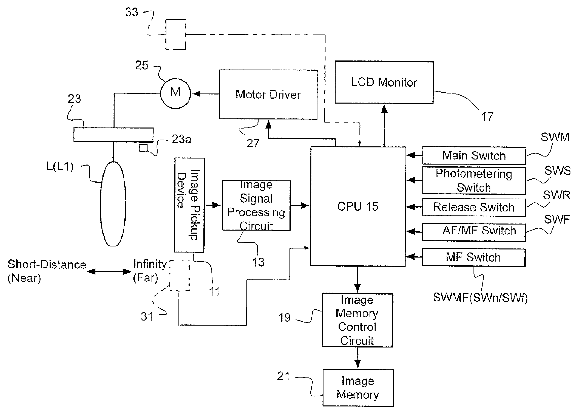
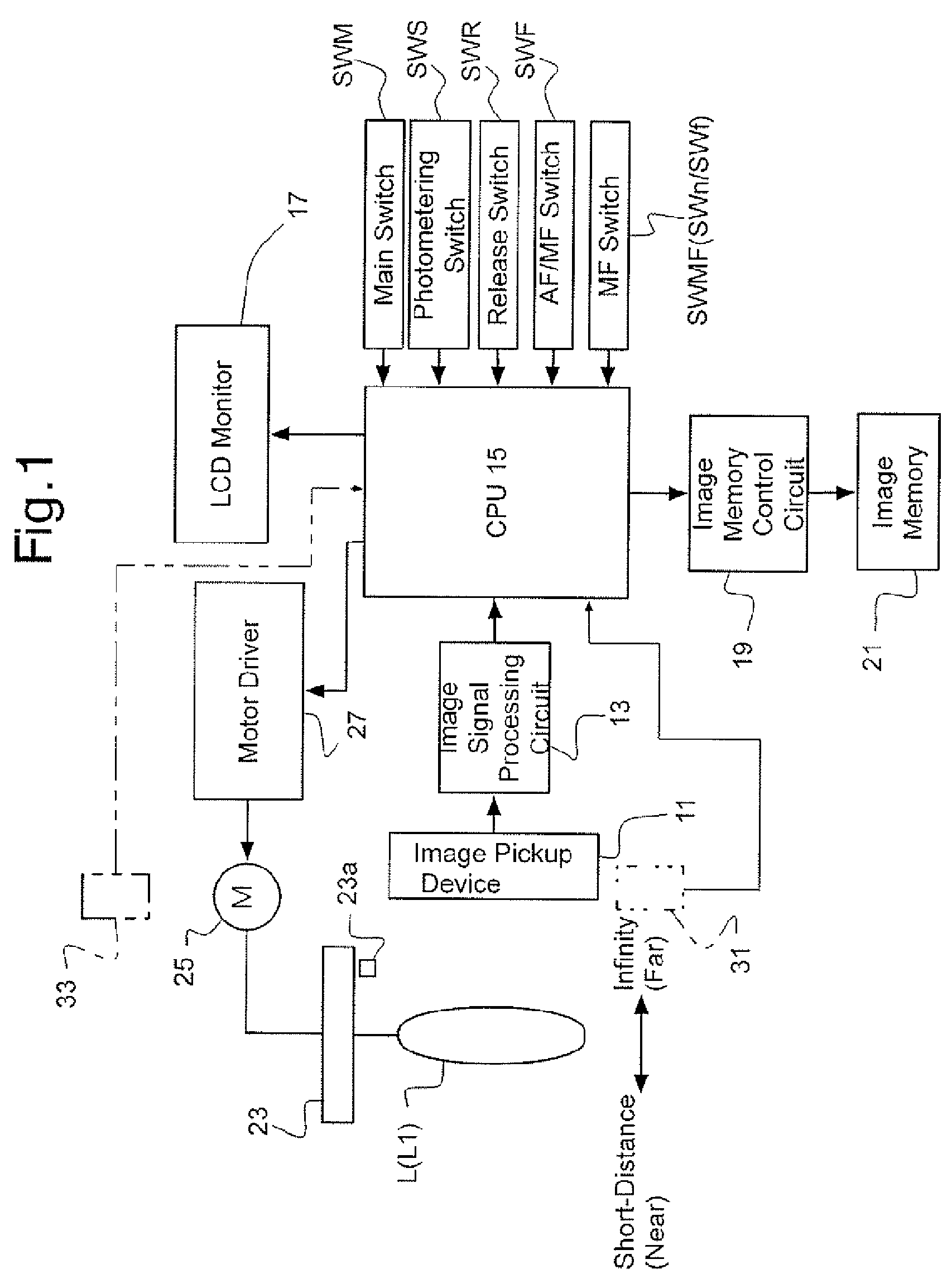
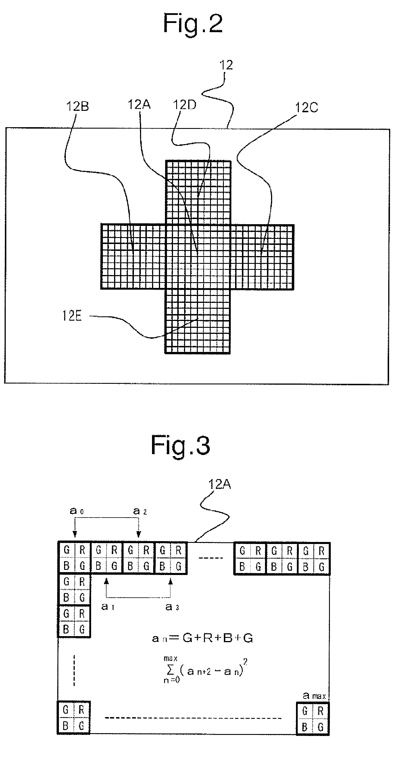
[0031]FIG. 1 is a block diagram of essential elements of an embodiment of a compact digital camera to which a focus adjustment apparatus of the present invention is applied. This compact digital camera is provided with a photographing lens L including a focusing lens group (movable lens group) L1, and an image pickup device (CCD image sensor) 11 serving as an imaging device. An object image is formed on a light receiving surface 12 (see FIG. 2) of the image pickup device 11 via the photographing lens L. The focusing lens group L1 is supported to be freely movable between the infinite focus position (far side / position for bringing an object at infinity into focus) and the closest (shortest) focus position (near side / position for bringing an object at the shortest distance in working range into focus) and is driven stepwise by an AF motor 25 under control of a motor driver 27. The motor driver 27 operates on a command from a CPU (controller / focus detection device) 15 when the digital ...


PUM


Abstract

A focus adjustment apparatus includes an imaging device for capturing object images via a photographing lens; a lens driving device which moves a focusing lens group; a manual focus adjustment device which actuates the lens driving device to move the focusing lens group in response to a manual operation; a focus detection device for making the imaging device capture an object image to determine a contrast value thereof each time the focusing lens group moves by a predetermined amount of movement due to the manual operation, and for detecting an in-focus position of the focusing lens group in accordance with contrast values detected by the focus detection device at different lens positions; and a controller which moves the focusing lens group to the in-focus position via the lens driving device if a deviation exists between a stopped position and the in-focus position.

Description

BACKGROUND OF THE INVENTION[0001]1. Field of the Invention[0002]The present invention relates to a focus adjustment apparatus which includes a manual focus system and an autofocus system.[0003]2. Description of the Prior Art[0004]Compact digital cameras which include both a manual focus capability (manual focus system) for manually adjusting the focus by a photographer and a contrast detection autofocus capability (autofocus system) for automatically detecting a focus in accordance with contrasts of an object image are known in the art. In typical compact digital cameras, object images are captured at predetermined intervals and are indicated on an LCD panel. The manual focus system incorporated in such compact digital cameras is constructed so that a motor starts rotating upon a focus control switch being operated to move a focusing lens group in a direction toward a position thereof on the close-distance range side or the long-distance side by the rotation of the motor. In the cas...

Claims


Application Information

Patent Timeline
Patent Type & Authority Patents(United States)
IPC IPC(8): G02B7/02
CPCG02B7/36H04N5/23212H04N2101/00H04N9/07H04N9/045H04N23/673H04N23/10H04N23/12H04N25/134
Inventor NAKAHARA, NAOTO
Owner RICOH IMAGING COMPANY
Why Eureka
Try Eureka