Heating arrangement for a material testing device

a testing device and heat arrangement technology, applied in measurement devices, instruments, scientific instruments, etc., can solve problems such as thermal drift, affecting the accuracy of measurements, and introducing heat into measurements, so as to reduce the heat transmission to the headstock and improve the heat flow

Active Publication Date: 2019-10-08
ANTON PAAR TRITEC SA
View PDF15 Cites 0 Cited by
  • Summary
  • Abstract
  • Description
  • Claims
  • Application Information

AI Technical Summary

Benefits of technology

[0020]As a result, a concentrated beam of infrared radiation can be created from any convenient infrared emitting element, such as but not limited to a halogen lamp, a ceramic heater, a laser or similar, which can then be focused as desired upon the probe. With such an arrangement it is possible to achieve higher temperatures than with a laser, and the infrared radiation can be focused more or less sharply upon the probe as required so as to avoid localised hotspots.
[0034]Advantageously, the reflector of the probe heater is formed integrally with the heatsink, improving heat flow by eliminating the material junction between the reflector and the heatsink.

Problems solved by technology

However, the probe tip must equally be heated to the same temperature as the sample to prevent localised cooling of the hot sample causing thermal expansion of the tip and thermal contraction of the sample, which affects the accuracy of the measurements.
However, there is also the further constraint that the heating must be kept as localised as possible to the sample and to the tip so as to avoid heating the entire system, which would again affect the accuracy of the measurements by inducing thermal expansion in other components of the system.
Furthermore, this can introduce thermal drift into the measurements.
Such systems incorporating heating elements integrated into the probe tip are however not satisfactory: they are bulky and thus result in heating of a relatively large amount of material, which is undesirable both in terms of thermal expansion and also in terms of thermal inertia.
Significant thermal inertia results in time lags and thus control instability when manipulating the temperature of the tip.
Furthermore, the temperatures which can be achieved are somewhat limited, as are the temperatures at which measurement repeatability is good.
However, the maximum temperature attainable at the tip is approximately 500° C., which is inadequate for many applications.
Other known arrangements include heating the probe by induction, however this generates significant electromagnetic interference which can affect the operation of sensitive measurement devices.
However, none of these heating arrangements are suitable for use in a materials testing device for reasons of structural incompatibility or optical reasons.
Furthermore, none of the documents mentioned suggest either implicitly or explicitly the use of such arrangements for overcoming any of the drawbacks of existing heating arrangements for materials testing devices as discussed above.

Method used


Image

  • Heating arrangement for a material testing device
  • Heating arrangement for a material testing device
  • Heating arrangement for a material testing device

Examples


Embodiment Construction

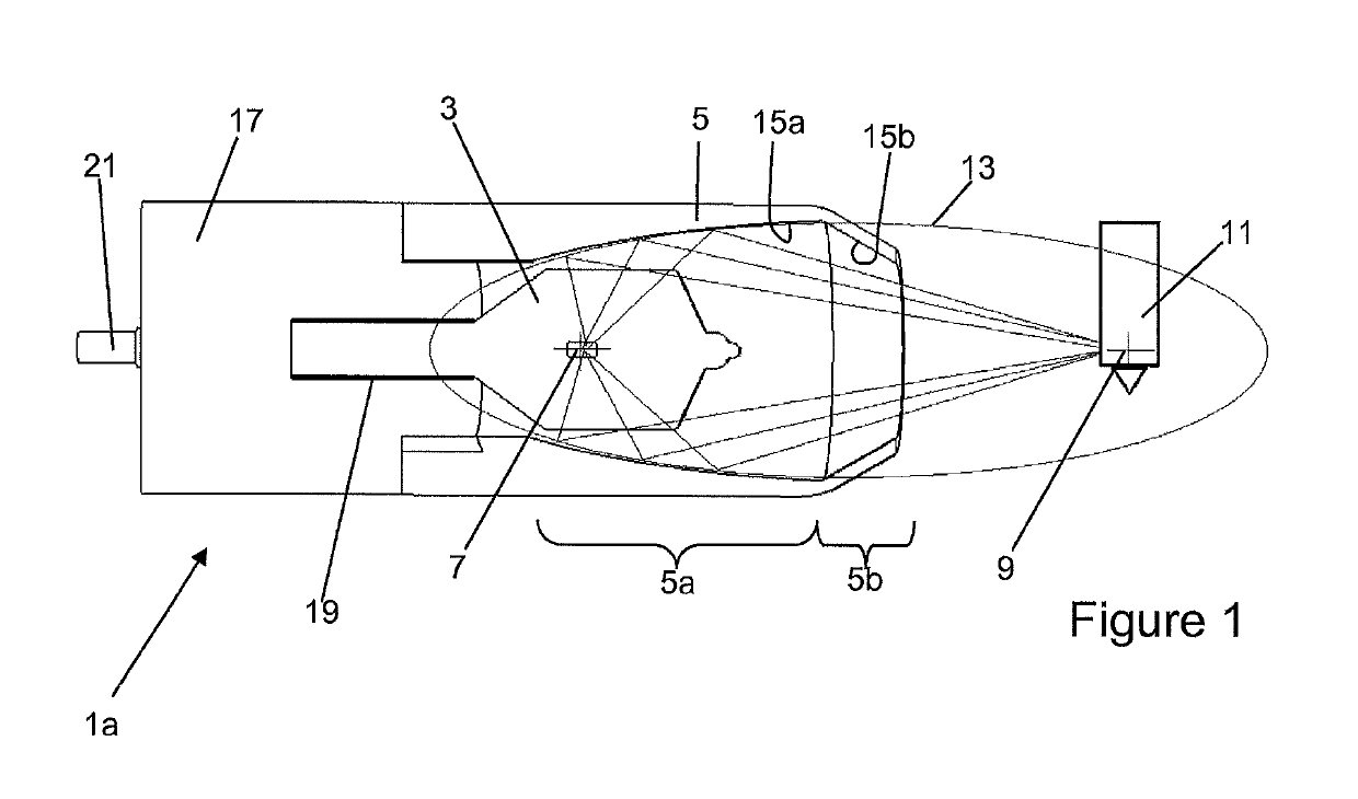
[0040]FIG. 1 illustrates schematically the basic principle of a probe heater 1a comprised in a heating arrangement according to the invention.

[0041]The heating arrangement comprises a probe heater 1a comprising an infrared emitting element 3 such as an incandescent lamp (e.g. a halogen lamp), a ceramic heating element, a laser, or similar. Halogen lamps are particularly advantageous because they are cheap, easily replaced, available off-the-shelf, and the filament can easily attain temperatures in the region of 3000 K at relatively low currents. Such an infrared emitting element 3 is illustrated in the present embodiment. Typical power would be around 150 W, however powers as low as 35 W are adequate for certain applications Furthermore, such lamps emit energy in both the visible and infrared wavelength ranges, with a broad spectrum, and have a low thermal inertia due to their low mass, and thus the low heat capacity, of the filament. Their temperature can thus be very easily and ve...


PUM

PropertyMeasurementUnit
temperatureaaaaaaaaaa
temperaturesaaaaaaaaaa

Abstract

Heating arrangement for a materials testing device, the materials testing device comprising at least one surface measurement probe adapted to be brought into contact with a surface of a sample, the heating arrangement comprising a probe heater comprising:an infrared emitting element adapted to emit infrared radiation;a reflector having a reflective surface arranged to direct said infrared radiation towards a distal end of said surface measurement probe.According to the invention, the reflector comprises a first focal point and a second focal point, the infrared emitting element being situated substantially at said first focal point.

Description

CROSS-REFERENCE TO RELATED APPLICATIONS[0001]This application is a § 371 national stage entry of International Application No. PCT / EP2015 / 075490, filed Nov. 2, 2015, which claims priority to European Patent Application No. 14191443.2, filed Nov. 3, 2014, the entire contents of which is incorporated herein by reference.TECHNICAL FIELD[0002]The present invention relates to the field of surface testing of materials. More particularly, it relates to a heating arrangement for a materials testing device such as an indenter.STATE OF THE ART[0003]Materials science requires detailed knowledge of mechanical properties of materials, surfaces and coatings even on the nano-scale, and also the temperature dependence of these properties. Indentation testing allows determination of Young's modulus, hardness, strain rate sensitivity, tribological properties etc. on any scale. Measurements at micrometer and nanometer scales are particularly useful, and can permit measurements of the properties of sin...

Claims


Application Information

Patent Timeline
Patent Type & Authority Patents(United States)
IPC IPC(8): G01N3/04G01N21/37G01N3/42B01L7/00
CPCG01N21/37G01N3/04B01L7/52G01N2203/0226G01N3/42
Inventor BELLATON, BERTRANDCONTE, MARCELLO
Owner ANTON PAAR TRITEC SA
Why Eureka
Try Eureka