Airway balloon dilator

a balloon dilator and airway technology, applied in balloon catheters, other medical devices, surgery, etc., can solve the problems of tracheal stenosis, prior intubation, and one of the most challenging problems of head and neck surgeons, so as to quickly restore laryngeal, tracheal or bronchial luminal patency, and avoid excessive trauma to patients. , the effect of quick re-establishmen

Active Publication Date: 2009-09-22
PEDIATRIC AIRWAY INNOVATIONS LLC
View PDF20 Cites 31 Cited by
  • Summary
  • Abstract
  • Description
  • Claims
  • Application Information

AI Technical Summary

Benefits of technology

[0010]The present invention provides an airway balloon dilator for use to quickly re-establish laryngeal, tracheal or bronchial luminal patency to restore airflow in a way that avoids excessive trauma to the patient.

Problems solved by technology

Management of stenosis of the trachea and bronchi, including laryngotracheal and subglottic stenosis, is one of the most challenging problems for the head and neck surgeon.
In addition, long term intubation has become an accepted alternative to tracheotomy, leading to more and more incidences of tracheal stenosis.
Adults usually have a history of prior intubation with symptoms of progressive shortness of breath and noisy breathing.
That is, very small increases in the luminal diameter of the airway can lead to large increases in airflow through the lungs.
Although safe when performed by a skilled clinician, such a procedure sometimes induces unwanted trauma to the airway in the form of deep lacerations and hemoptysis.
Further, current dilation practices do not permit dilation of a tracheal stenosis that is distal to a narrowing of the proximal airway (i.e. a mild subglottic stenosis).
Current airway balloon dilation procedures are typically carried out using angioplasty balloons; however, several limitations to the use of angioplasty balloons become evident when used on the airway.
For example, it may be difficult to adequately ventilate the patient during the dilation period, since the typical angioplasty balloon does not include a connection to an oxygen source.
Further, the shape of the angioplasty balloon may predispose the balloon to slide out of place during dilation, or the balloon may be limited to the amount of pressure that can be applied before the balloon bursts.
Other factors associated with failure of airway balloon dilation include previous attempts at endoscopic repair, circumferential scarring, and loss of cartilaginous support.

Method used


Image

  • Airway balloon dilator
  • Airway balloon dilator
  • Airway balloon dilator

Examples


Embodiment Construction

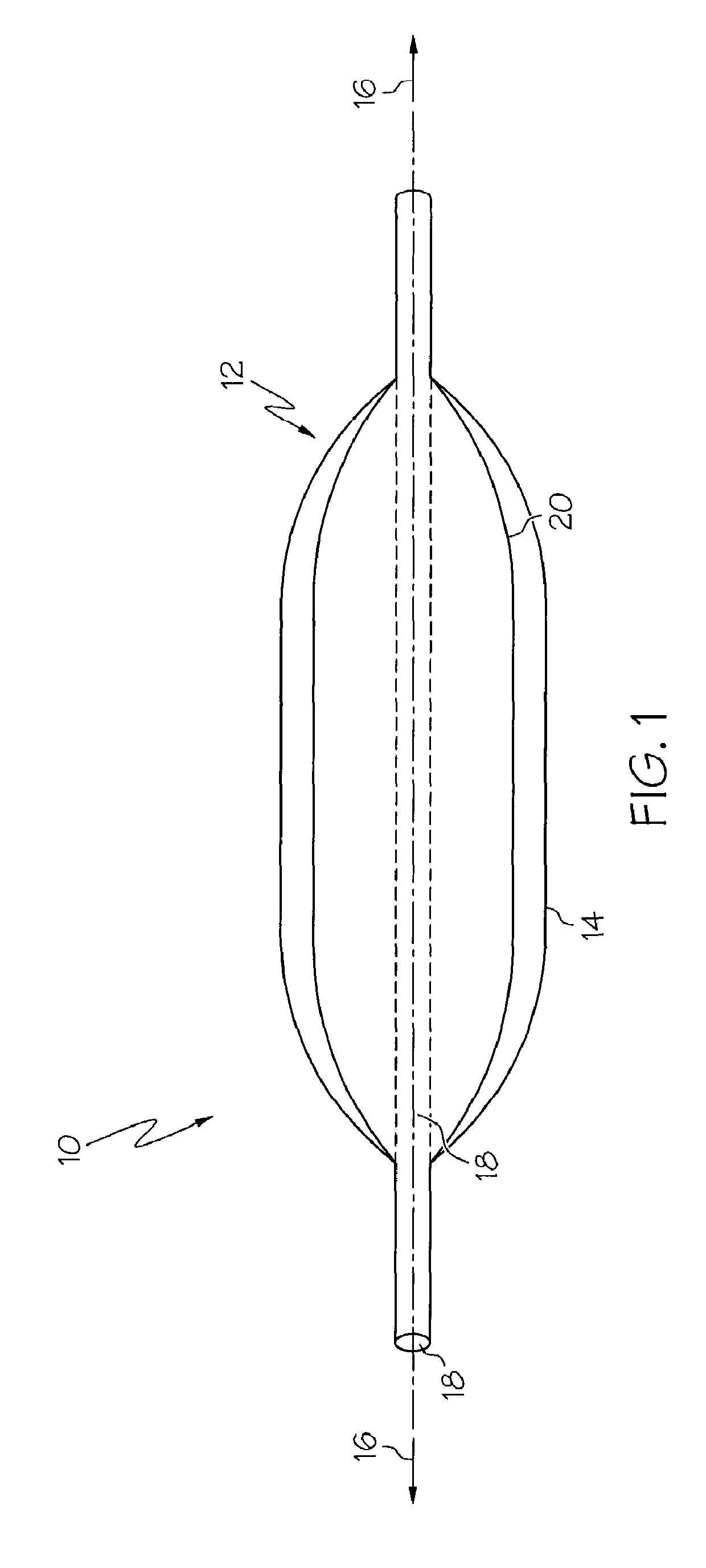
[0019]As illustrated in FIG. 1, one embodiment of the present invention is an apparatus 10 for performing an airway balloon dilation procedure at the site of a stenosis in the airway of a patient, the apparatus comprising an inflatable outer balloon 12 which has an external surface 14. The apparatus also comprises a central axis 16, a hollow core 18, and at least one inflatable inner balloon 20 adapted to inflate inside the outer balloon 12. The apparatus 10 is typically insertable into the airway of a patient for movement of the balloons 12, 20 between a deflated configuration and an inflated configuration. Further, the inner balloon 20 is designed to inflate inside the outer balloon 12 yet separately from the outer balloon, adding the ability of the apparatus to produce high dilation pressures without balloon rupture.

[0020]As shown in FIG. 1, the hollow core 18 traverses the entire apparatus 10. Typically the hollow core connects via a proximal ISO connector to an oxygen source su...


PUM


Abstract

A medical apparatus for widening a stenosis in the airway of a patient which includes a central hollow core, an inflatable outer balloon, and at least one inner balloon inside the outer balloon. The apparatus also can include a flexible support member mounted on the external surface of the outer balloon with at least one microsurgical blade. The outer balloon can be dumbbell-shaped to keep the balloon in position over the stenosis when the balloon is inflated. The hollow core allows the patient to be ventilated during the procedure, the inner balloon(s) allow higher dilation pressures to be generated from inside the outer balloon, and the blade can form an effective cutting edge upon inflation of the outer balloon.

Description

CROSS-REFERENCE TO RELATED APPLICATION[0001]This application is a continuation-in-part of application Ser. No. 11 / 231,457, filed on Sep. 21, 2005 now abandoned.FIELD OF THE INVENTION[0002]The present invention relates to medical care for the larynx, trachea or bronchi to relieve a stenosis. In particular, the invention relates to a device for performing dilation of the larynx, trachea or bronchi.BACKGROUND OF THE INVENTION[0003]Management of stenosis of the trachea and bronchi, including laryngotracheal and subglottic stenosis, is one of the most challenging problems for the head and neck surgeon. Subglottic stenosis is a congenital or acquired narrowing of the subglottic airway. In the early twentieth century subglottic stenosis was rare, and most cases occurred in adults. In the 1960's the incidence of acquired subglottic stenosis began to dramatically increase in the neonatal population, most likely the result of increased survival of low-birth-weight infants and the increased us...

Claims


Application Information

Patent Timeline
Patent Type & Authority Patents(United States)
IPC IPC(8): A61M29/00A61M25/10
CPCA61M25/104A61M2025/1086A61M2210/1035A61M2210/1028A61M2210/1032A61M2025/109
Inventor RUTTER, MICHAEL JOHN
Owner PEDIATRIC AIRWAY INNOVATIONS LLC
Why Eureka
Try Eureka