Image processing apparatus, method for controlling image processing apparatus

a technology of image processing and control apparatus, applied in the direction of electrical apparatus, instruments, computing, etc., can solve the problems of inability to meet the need for even higher scanning speed and cannot expect to dramatically increase the processing speed

Inactive Publication Date: 2009-11-10
CANON KK
View PDF10 Cites 6 Cited by
  • Summary
  • Abstract
  • Description
  • Claims
  • Application Information

AI Technical Summary

Problems solved by technology

For this reason, also in a scan of an image including many white areas, the traveling speed of the scanner head results in a bottleneck, so that the speed of processing cannot be expected to dramatically increase.
For these reasons, the prior art cannot to respond to the need for even higher scanning speed.

Method used


Image

  • Image processing apparatus, method for controlling image processing apparatus
  • Image processing apparatus, method for controlling image processing apparatus
  • Image processing apparatus, method for controlling image processing apparatus

Examples


first embodiment

100>

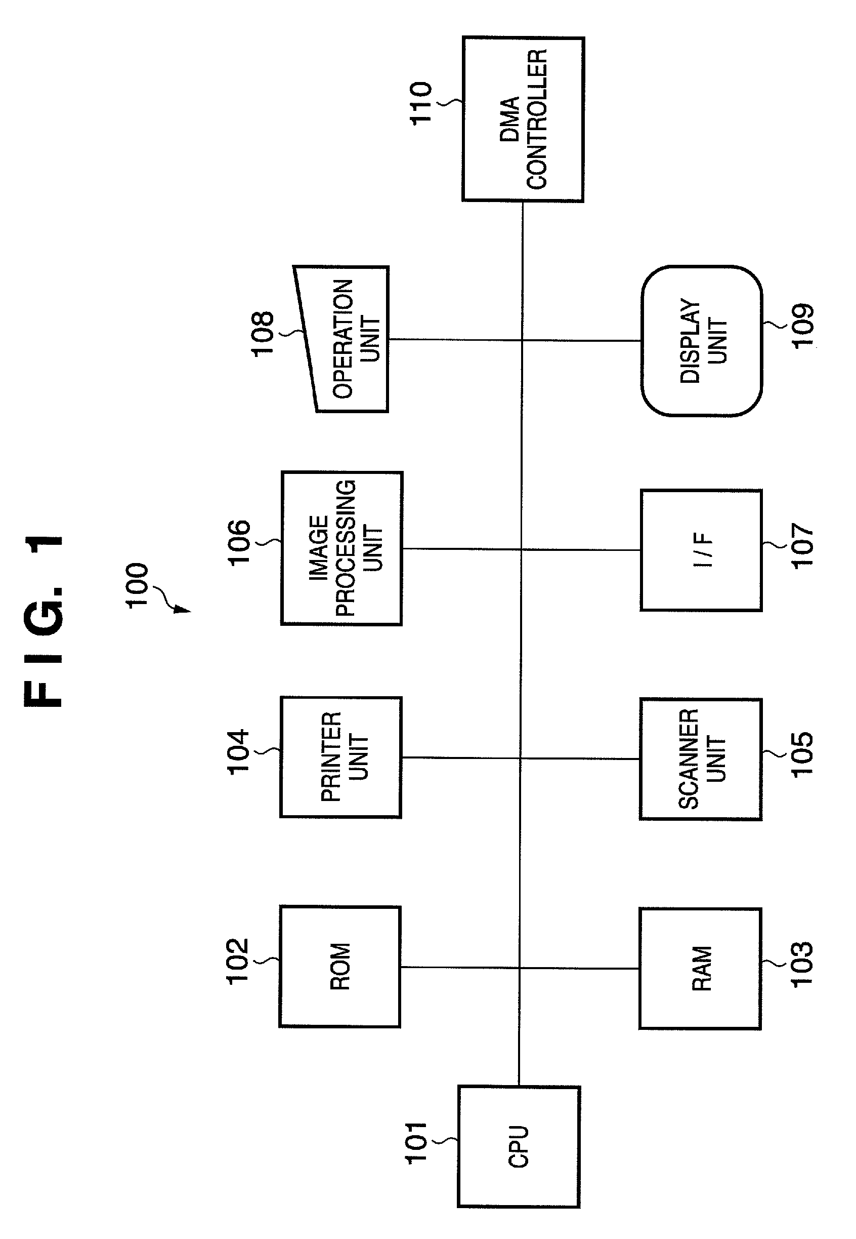
[0037]FIG. 1 is a functional block diagram showing the configuration of a multifunction printer (MFP 100) which is an example of an image processing apparatus to which the present invention can be applied.

[0038]A CPU 101 is a processor for controlling the overall MFP 100. The MFP 100 is controlled by running a program (firmware) stored in ROM 102.

[0039]The ROM 102 is nonvolatile memory for storing the program for controlling the MFP 100.

[0040]RAM 103 is nonvolatile memory which is used as a work area when the CPU 101 runs the program stored in the ROM 102. The RAM 103 is also used as buffer memory for temporarily storing image data having been scanned by a scanner unit 105.

[0041]A printer unit 104 prints image data on a sheet of paper, an OHP sheet, and so on (hereinafter, will be referred to as a “printing medium”). In the present embodiment, the printer unit 104 is an inkjet printer which includes a printhead, a motor, and an ink cartridge. The printer unit 104 causes a carria...

second embodiment

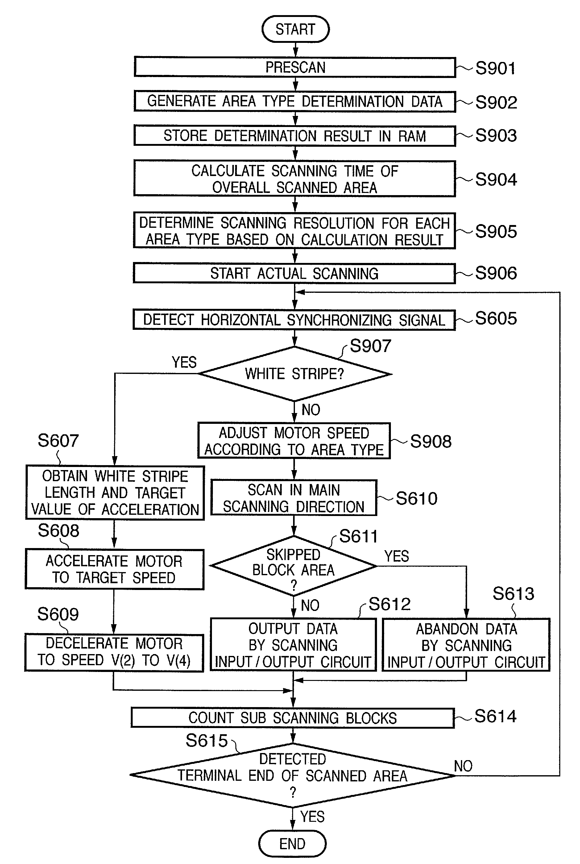
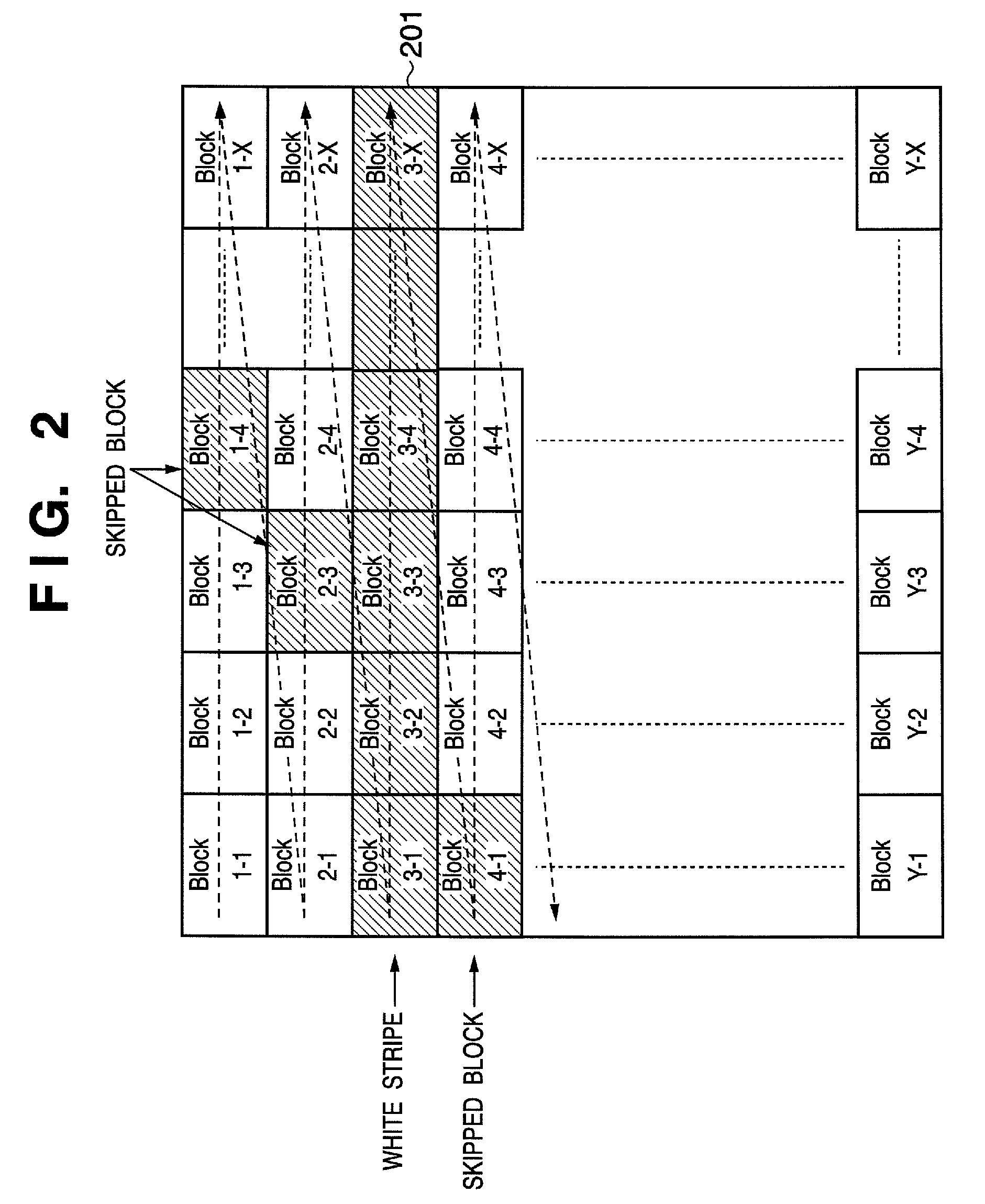
[0097]In First Embodiment, the MFP 100 of FIG. 1 generates the white area determination data 301 of FIG. 3 only based on a determination whether the prescan image data 201 of FIG. 2 is a white area or not, and the scanning speed is increased. In Second Embodiment, the area type of each block of prescan image data 701 (FIG. 7) is determined. The area type includes an area including only a text, an area including only an image, and a mixed region including a text and an image. In the explanation of the present embodiment, as described above, an “image” includes a “text image” in principle and an “area only including an image” and an “image region” include no text image.

[0098]In the present embodiment, a scanner unit 105 determines a scanning resolution based on an area type (to be precise, a stripe type generated based on the area type), so that the scan image data 302 (FIG. 3) is obtained with high image quality.

[0099]Further, in the present embodiment, an MFP 100 may be identical in...


PUM


Abstract

A scanner unit 105 of an MFP 100 performs prescanning and generates white area determination data 301. Next, at the scanning operation, the scanner unit 105 refers to the white area determination data 301 to detect a white stripe. In this area, a motor is driven at high speed.

Description

BACKGROUND OF THE INVENTION[0001]1. Field of the Invention[0002]The present invention relates to a technique for efficiently scanning an image in an image processing apparatus including an image scanning unit.[0003]2. Description of the Related Art[0004]Currently multifunction printers (MFPS) including scanner units and printer units are widely available as image processing apparatuses. The scanner head of a scanner unit in an MFP includes an image sensor such as a CCD and a CIS (contact image sensor). The printer unit of an MFP includes an inkjet printer or a laser printer.[0005]An image processing circuit or the CPU of an MFP performs image processing on digital image data having been generated by scanning an image through the scanner unit of the MFP, and a printer unit prints the image using the processed digital image data. The MFP thus realizes a copy function.[0006]An MFP generally includes memory in which three areas are allocated as an input buffer for storing digital image ...

Claims


Application Information

Patent Timeline
Patent Type & Authority Patents(United States)
IPC IPC(8): H04N1/04G06K9/32H04N1/387
CPCH04N1/0473H04N2201/0416H04N2201/04794H04N2201/04755H04N2201/04791H04N2201/044
Inventor KIKUCHI, AKITOSHI
Owner CANON KK
Why Eureka
Try Eureka