
Gas deflector for an air-bag

a technology of airbags and gas deflectors, which is applied in the direction of vehicle components, pedestrian/occupant safety arrangements, vehicular safety arrangments, etc., can solve the problem of complicated requirements and achieve the effect of improving the gas deflector

Active Publication Date: 2010-01-12
AUTOLIV DEV AB
View PDF22 Cites 13 Cited by
  • Summary
  • Abstract
  • Description
  • Claims
  • Application Information

AI Technical Summary

Problems solved by technology

In some cases, the requirement is more complicated, since the flow of gas flowing in one direction substantially parallel to the gas generator is to be greater than the flow of gas flowing in the opposite substantially parallel direction.

Method used


Image

  • Gas deflector for an air-bag
  • Gas deflector for an air-bag
  • Gas deflector for an air-bag

Examples


Embodiment Construction

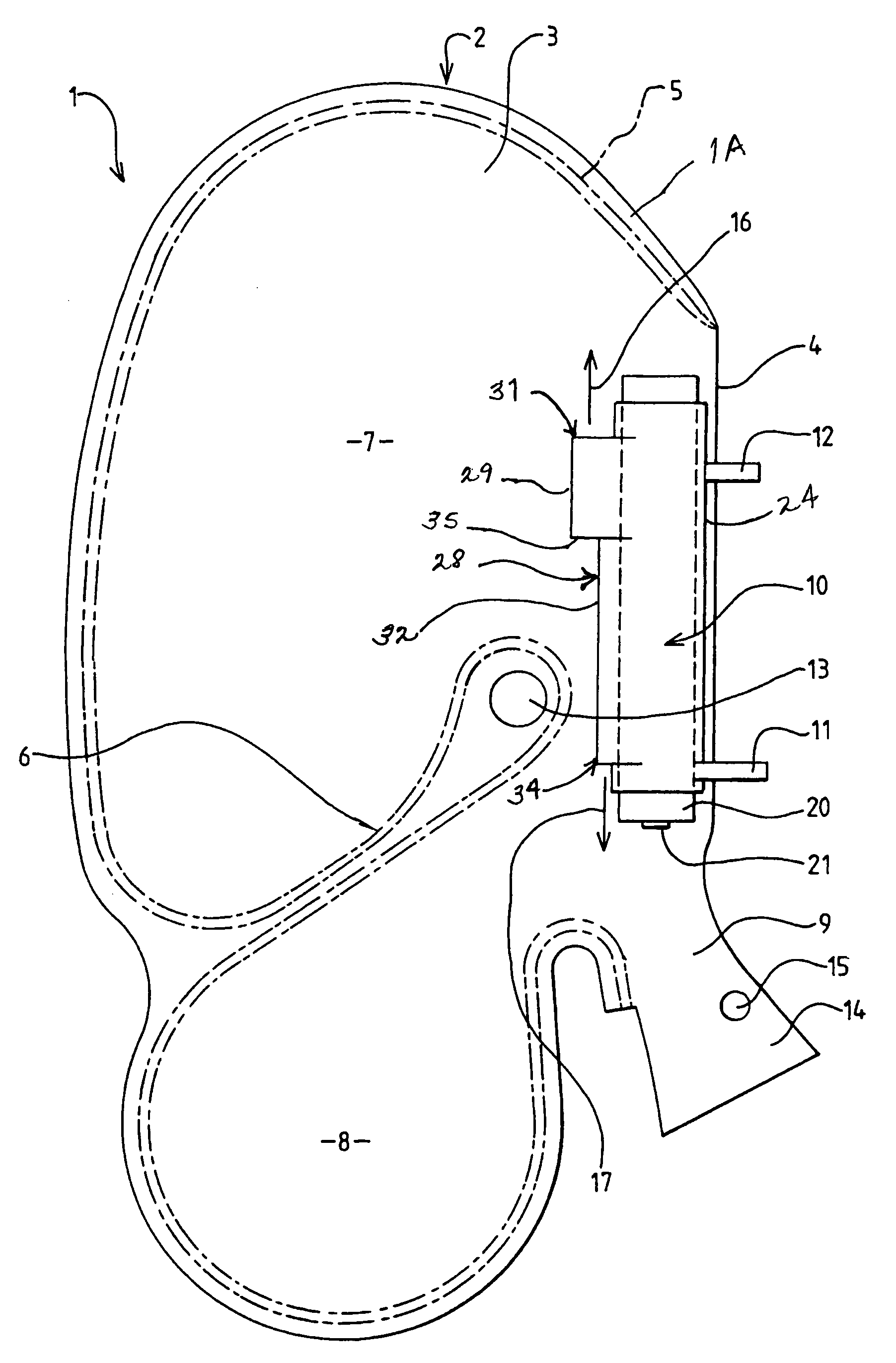
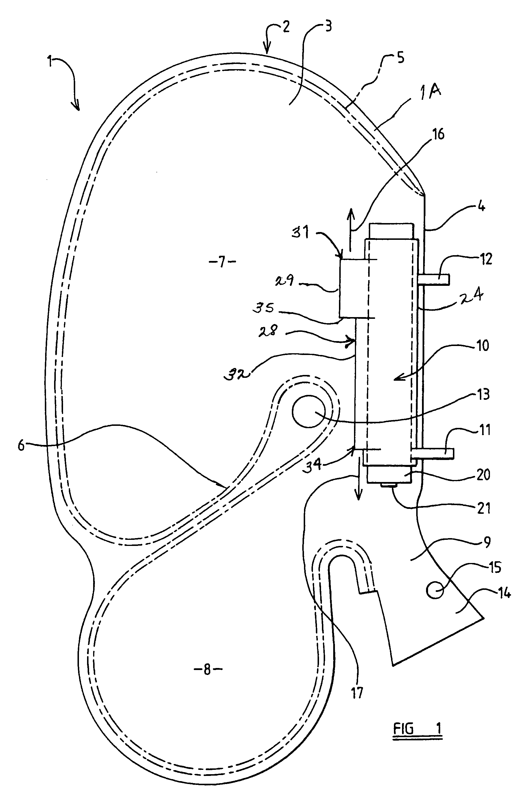
[0021]Referring initially to FIG. 1 of the accompanying drawings, a side air-bag assembly 1 is illustrated. The side air-bag assembly 1 is intended to be mounted in position in the back rest of a vehicle seat or in the side wall of a motor vehicle adjacent to the vehicle seat so that the air-bag, when inflated, is located between the seat occupant and a side part of the motor vehicle. The air-bag assembly includes an air-bag 1A formed from two super-imposed layers of fabric 2 and 3 which, in the described embodiment, are interconnected by a notional fold or hinge line 4. Each of the layers of fabric 2 and 3 is of the same shape and size, and the layers are folded about the notional fold line 4 and are interconnected by means of a seam 5. The seam 5 extends around the periphery of the super-imposed layers 3 and 4 and includes a re-entrant portion 6 which extends substantially transversally across the air-bag 1A, dividing the air-bag into an upper chamber 7 and a lower chamber 8. The ...


PUM


Abstract

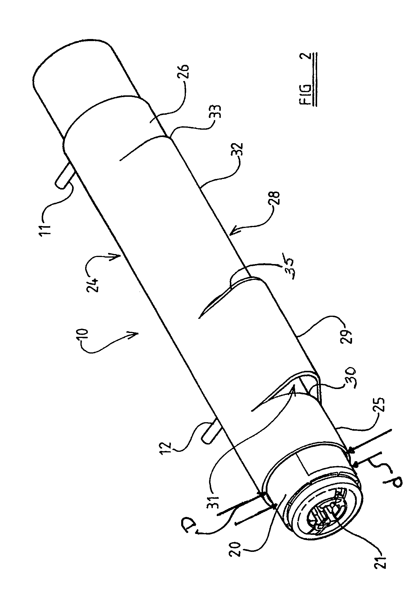
A gas deflector (24) is disclosed for use with a cylindrical gas generator (20). The gas deflector (24) comprises a generally tubular housing to accommodate the cylindrical gas generator (20). The housing has two terminal portions (25, 26) of generally circular cross-section and has an intermediate region provided with an outwardly-extending formation (28). The outwardly-extending formation (28) defines, at either end thereof, an opening (31, 34) through which gas may flow in the direction substantially parallel to the axis of the housing.

Description

CROSS REFERENCE TO RELATED APPLICATIONS[0001]This application claims priority to Great Britain patent application 0322519.0, filed Sep. 25, 2003 and PCT / SE2004 / 001266 filed Sep. 3, 2004.FIELD OF THE INVENTION[0002]The present invention relates to a gas deflector, and more particularly relates to a gas deflector for use with a gas generator configured to supply gas to inflate an air-bag, such as an air-bag provided in a motor vehicle to provide protection to a vehicle occupant in the event that a vehicle collision should occur.[0003]Many gas generators utilised as inflators for air-bags are of a generally cylindrical form. Typically such a gas generator is provided with a plurality of apertures formed in the outer wall of the gas generator, and on actuation of the gas generator, gas flows in a radially outward direction through these apertures. However, in many cases, it is most desirable for gas from the gas generator to flow into the associated air-bag with a flow direction which i...

Claims


Application Information

Patent Timeline
Patent Type & Authority Patents(United States)
IPC IPC(8): B60R21/26B60R21/233B60R21/217B60R21/261
CPCB60R21/26B60R21/261B60R21/2171
Inventor KLOSS, MARKUSHABERZETTL, ANDREAS
Owner AUTOLIV DEV AB
Learn More