Short-circuit charge-sharing technique for integrated circuit devices

a short-circuit, charge-sharing technology, applied in the direction of power consumption reduction, automatic control, instruments, etc., can solve the problems of isub>top/sub>, two circuit blocks may not be balanced, and the level shift of the charge-sharing circuit is easy to achieve. , to achieve the effect of easy enabling and disabling of the charge-sharing circui

Active Publication Date: 2010-01-19
INVENSAS CORP
View PDF16 Cites 9 Cited by
  • Summary
  • Abstract
  • Description
  • Claims
  • Application Information

AI Technical Summary

Benefits of technology

[0007]In an IC incorporating a memory array for example, if two sets of read data lines in a read pipeline stage path are to be charge shared with each other, the read clock (commonly labeled RCLK) that is used to time the first and second set of read data lines can also be used to generate the gate voltage of the charge-sharing shorting device. This allows for easy enabling and disabling of the charge-sharing circuits. Also, by using the same clock signal, or a signal of the same clock frequency as that activating the signal lines that are to be charge-shared, automatic tracking will occur between the amount of charge needed and the amount of charge that is shared.

Problems solved by technology

There are at least two limitations with this approach, one of which is that the two circuit blocks may not be balanced to where the current ITOP is not similar to IBOTTOM.
This results in a drift of these internal power supply nodes and a shift in their levels depending on the amount of time each circuit is active.
This can be overcome with a regulator and hold circuit however, efficiency of the charge-sharing operation quickly decreases with this current imbalance.
Another limitation of this technique exists when something other than an equal fraction of the supply voltage is desired to supply voltage for the circuit blocks.

Method used


Image

  • Short-circuit charge-sharing technique for integrated circuit devices
  • Short-circuit charge-sharing technique for integrated circuit devices
  • Short-circuit charge-sharing technique for integrated circuit devices

Examples


Embodiment Construction

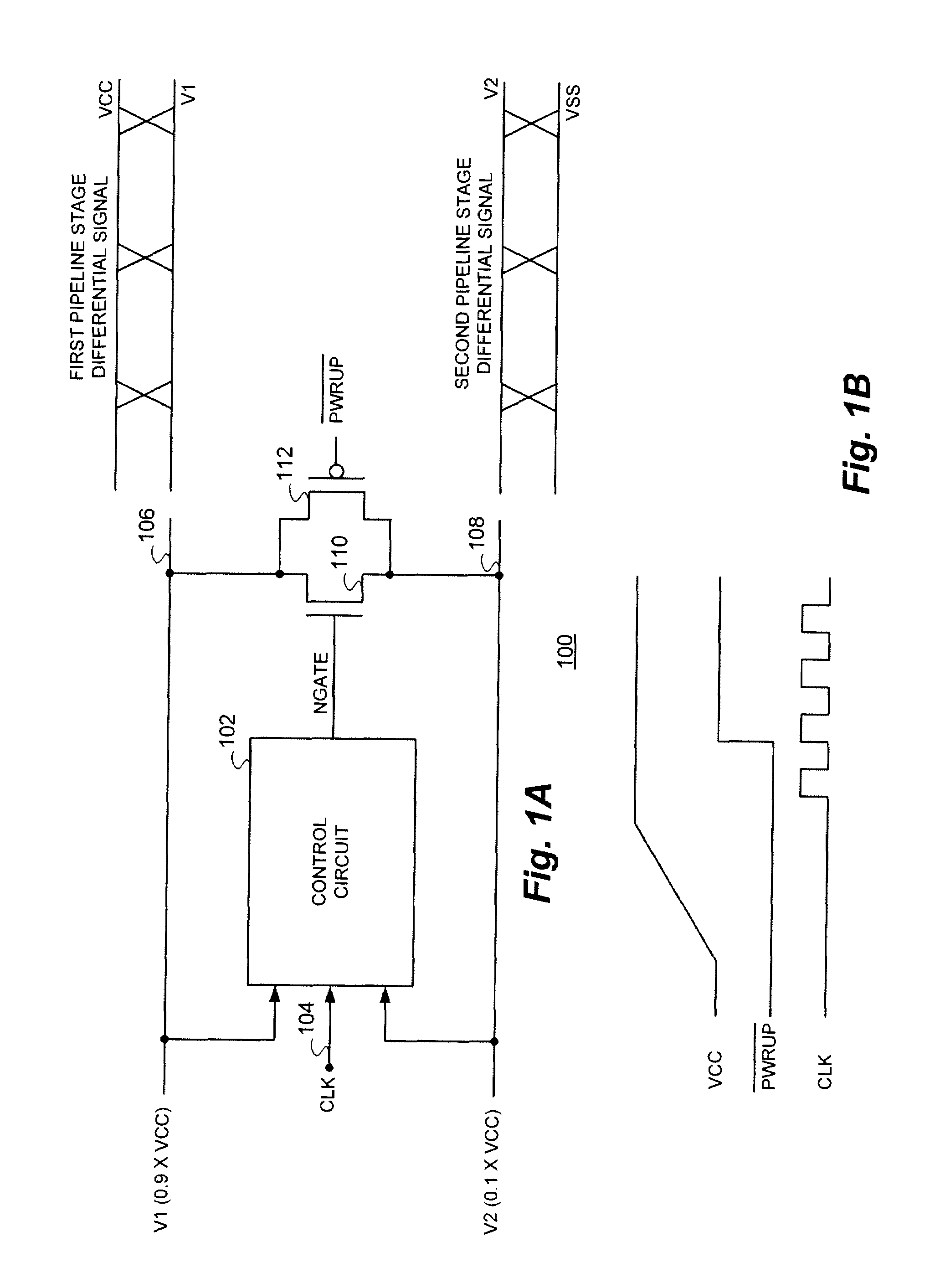
[0018]With reference now to FIG. 1A, a functional block diagram of a representative circuit 100 implementation of the short-circuit charge-sharing technique of the present invention is shown. The circuit 100 receives a voltage level V1, which in the exemplary implementation shown is substantially equal to 0.9×VCC and a voltage level V2 substantially equal to 0.1×VCC.

[0019]The V1 and V2 voltage levels are supplied on lines 106 and 108 as inputs to a control circuit 102. An exemplary implementation of the control circuit 102 will be described more fully hereinafter. The control circuit 102 also receives a clock (CLK) signal input on line 104 and is operational to provide a gating signal to the control terminal of transistor 110 which is coupled between lines 106 and 108. In the representative embodiment of a circuit 100 in accordance with the technique of the present invention illustrated, transistor 110 is illustrated as an N-channel device. Transistor 112 is illustrated as a P-chann...


PUM


Abstract

A short-circuit charge-sharing technique which allows charge-sharing between two or more circuits with a simple shorting transistor controlled to achieve the desired operating voltage levels. The shorting transistor which can be either a P-channel Metal Oxide Semiconductor (PMOS) or an N-channel Metal Oxide Semiconductor (NMOS) device and can be controlled utilizing the same clock that enables the drive of the signals between which charge-sharing occurs. In operation, the desired operating voltage levels can be regulated by increasing and decreasing the pulse width of the control circuit output to the gate of the shorting transistor.

Description

CROSS REFERENCE TO RELATED PATENT APPLICATIONS[0001]The present invention is related to the subject matter disclosed in U.S. patent applications Ser. No. 11 / 625,728, filed Jan. 22, 2007 for: “Switched Capacitor Charge-sharing Technique for Integrated Circuit Devices Enabling Signal Generation of Disparate Selected Signal Values” and Ser. No. 11 / 854,422, filed Sep. 12, 2007 for: “Data Bus Charge-Sharing Technique for Integrated Circuit Devices”, the disclosures of which are herein specifically incorporated by this reference in their entirety.BACKGROUND OF THE INVENTION[0002]The present invention relates, in general, to the field of integrated circuit (IC) devices having a need to conserve operating power. More particularly, the present invention relates to a short-circuit charge-sharing technique operative to conserve integrated circuit device operating power.[0003]Power consumption is becoming one of the largest concerns for today's integrated circuit devices. Charge-sharing, or cha...

Claims


Application Information

Patent Timeline
Patent Type & Authority Patents(United States)
IPC IPC(8): G05F3/02
CPCH03K19/0019
Inventor PARRIS, MICHAEL C.HARDEE, KIM C.
Owner INVENSAS CORP
Why Eureka
Try Eureka