Mechanism for biaxial rotation of a wing and vehicle containing such mechanism

a technology of wing and mechanism, which is applied in the field of mechanism for biaxial rotation of wing and vehicle, can solve the problems of substantial reduction of the Reynolds number and aerodynamic lift of traditional flying vehicles

Inactive Publication Date: 2010-01-26
DELAWARE UNIV OF A DE
View PDF7 Cites 41 Cited by
  • Summary
  • Abstract
  • Description
  • Claims
  • Application Information

AI Technical Summary

Problems solved by technology

Unfortunately, the Reynolds number and the aerodynamic lift of traditional flying vehicles decreases substantially as the wing length of the vehicles decreases.

Method used


Image

  • Mechanism for biaxial rotation of a wing and vehicle containing such mechanism
  • Mechanism for biaxial rotation of a wing and vehicle containing such mechanism
  • Mechanism for biaxial rotation of a wing and vehicle containing such mechanism

Examples


Embodiment Construction

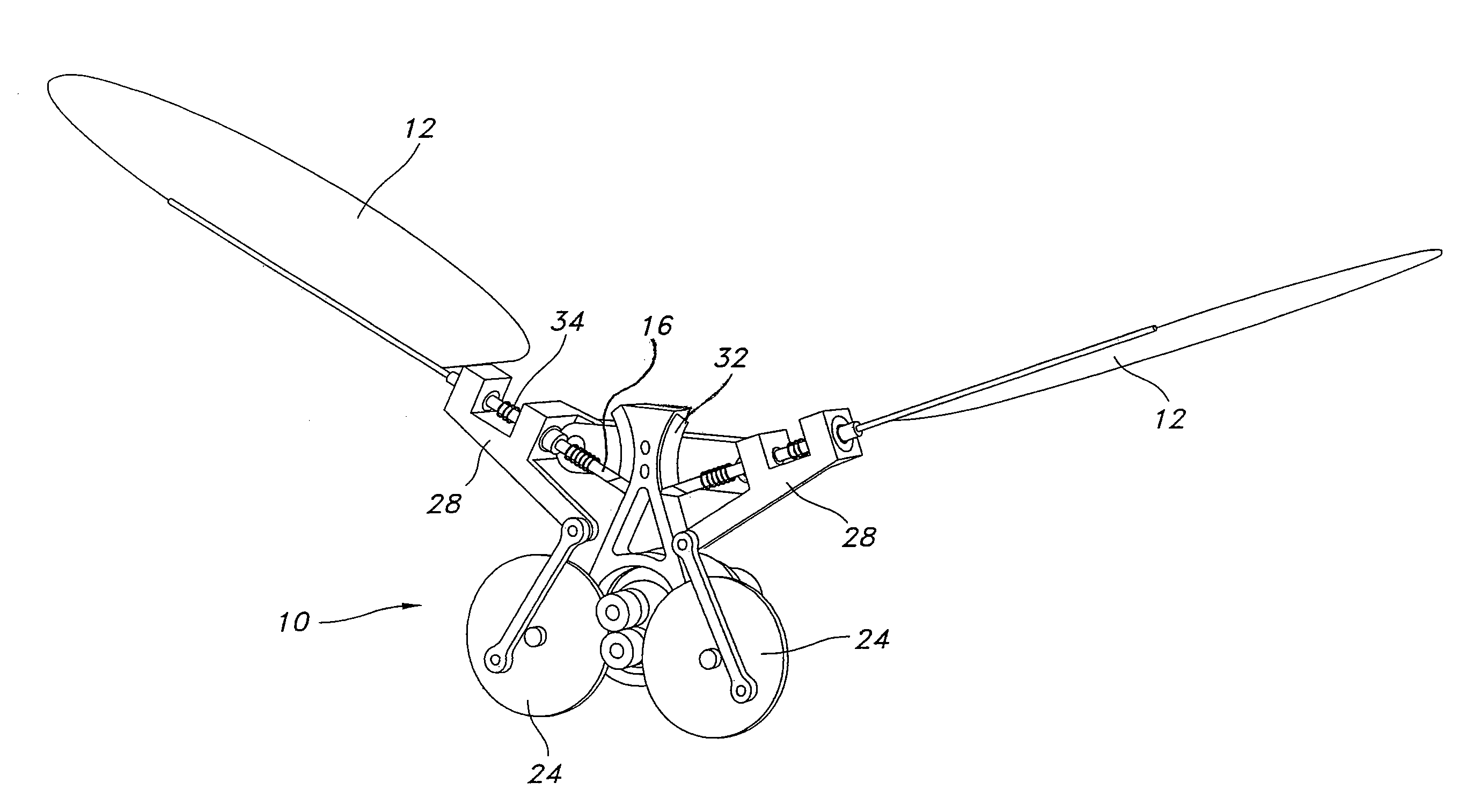
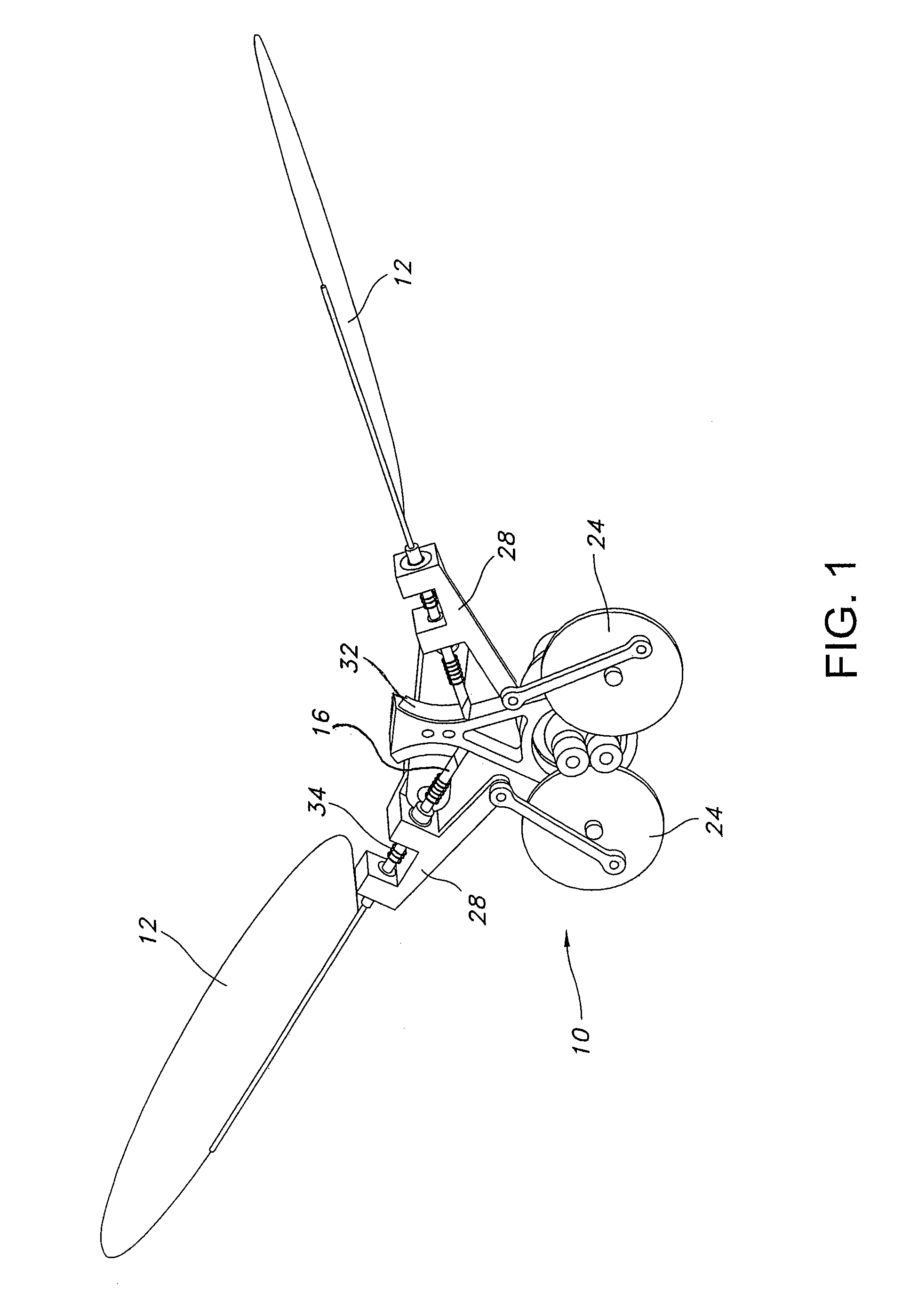
[0020]In an attempt to mimic the wing motion of smaller birds and insects, designs of ornithopters that can rotate the wings about two orthogonal axes are described. An exemplary ornithopter 10 is shown in FIG. 1. The ornithopters described herein have an aerodynamically advantageous wing motion; a light-weight and compact mechanism design; and a minimum number of actuators. The designs described herein advantageously comprise a flapping mechanism that creates wing rotation about two orthogonal axes, using a single actuator to create rotations about both axes for both wings.

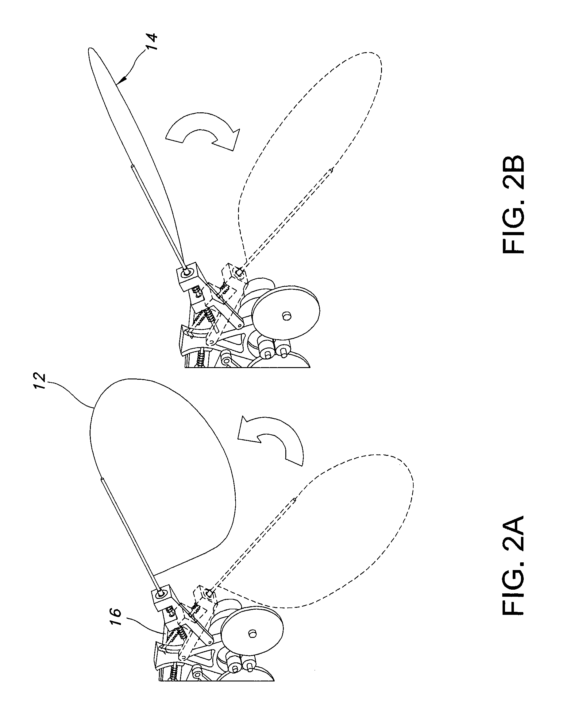
[0021]The mechanism creates a motion similar to insects and hummingbirds by quickly rotating the wing at the top and bottom of the up and down stroke. FIGS. 2A and 2B illustrate this motion. While wing 12 is translating downwards during flapping, the wing's flat surface 14 is perpendicular to the direction of the wing motion, pulling the air along with it generating positive lift, as shown in FIG. 2B. At the bott...


PUM


Abstract

A vehicle with wings and a mechanism for causing a flapping motion in wings. Each wing structure comprises a wing and a wing spar coupled to a follower via a resilient member. Each wing carrier is pivotally connected to the body and is configured to restrain lateral movement and permit rotation of the wing spar about a feathering axis. A biasing member provides torsional bias to each wing spar. A linkage, driven by an actuator, transmits cyclic motion that rotates the wing carrier about a flapping axis, which moves the follower along a follower path. A guide attached to the vehicle body lies in the path of each follower, and the follower and guide are shaped such that each wing spar has a first rotational position about its axis along a first portion of the follower path and a second rotational position along a second portion of the follower path.

Description

CROSS REFERENCE TO RELATED APPLICATIONS[0001]This application claims priority from U.S. Provisional Patent Application Ser. No. 60 / 734,606, filed Nov. 8, 2005, incorporated herein by reference.GOVERNMENT FUNDING[0002]The U.S. Government has a paid-up license in the present invention and the right in limited circumstances to require the patent owner to license others on reasonable terms as provided for by contract as awarded by the Army Research Office under Grant #W911NF-05-1-0066.BACKGROUND OF THE INVENTION[0003]In recent years, there has been a demand to reduce the size of unmanned air vehicles. The Defense Advanced Research Projects Agency (DARPA) defines the class of air vehicles measuring 15 cm or less in any dimension as micro air vehicles (MAVs). Possible applications of these vehicles range from civilian and military surveillance to search and rescue operations. Numerous research groups are actively developing designs of new MAVs. Examples of MAVs include the Black Widow, de...

Claims


Application Information

Patent Timeline
Patent Type & Authority Patents(United States)
IPC IPC(8): B64C33/02
CPCB64C33/02B64C39/028B64C2201/025B64U10/40B64U10/80
Inventor AGRAWAL, SUNIL K.MCINTOSH, SEAN H.KHAN, ZAEEM
Owner DELAWARE UNIV OF A DE
Why Eureka
Try Eureka