Trenching attachment having an internal combustion engine

a technology of internal combustion engine and pulling attachment, which is applied in the field of pulling attachments, can solve the problems of limited performance by the capabilities of this system, the auxiliary hydraulic system of the walk-behind mini-skid steer may not be able to provide as much digging power to the pulling attachment carried on the skid steer, and the small walk-behind unit tends to suffer from poor traction. to achieve the effect of facilitating rolling of the pulling attachmen

Inactive Publication Date: 2010-02-02
BLACK ALLAN
View PDF55 Cites 3 Cited by
  • Summary
  • Abstract
  • Description
  • Claims
  • Application Information

AI Technical Summary

Benefits of technology

[0011]Having its own dedicated engine, the trenching attachment is less dependent on the power take-off system of the working machine than a conventional trenching attachment that uses a hydraulic motor to power the trencher chain and relies exclusively on delivery of hydraulic fluid from the working machine for operation. In such a prior art arrangement, the capabilities of a particular working machine's hydraulic power take-off system limits the size of the hydraulic motor of a trenching attachment usable therewith, which in turn limits the size of the trenching boom that can be effectively powered for trenching operations. The digging chain entrained around the boom of a trencher attachment of the present invention, however, relies on the attachment's own dedicated engine for power, thus allowing an attachment of increased boom size to be produced for the same working machine by using a correspondingly larger engine on the attachment. At the same time, the use of the attachment in combination with a working machine benefits from improved traction provided by the working machine relative to a stand-alone walk behind trencher having a similarly sized boom and chain.

Problems solved by technology

Most of the smaller walk-behind units tend to suffer from poor traction relative to their larger ride-on counterparts.
However, a conventional trenching attachment typically relies on a power take-off system of the vehicle or working machine on which it is installed to power its trenching or digging chain, and thus is limited in performance by the capabilities of this system.
For example, the auxiliary hydraulic system of a walk behind mini-skid steer may not be capable of providing as much digging power to an attachment carried on the skid steer as could be produced using a stand-alone walk-behind gas-powered trencher.

Method used


Image

  • Trenching attachment having an internal combustion engine
  • Trenching attachment having an internal combustion engine
  • Trenching attachment having an internal combustion engine

Examples


Embodiment Construction

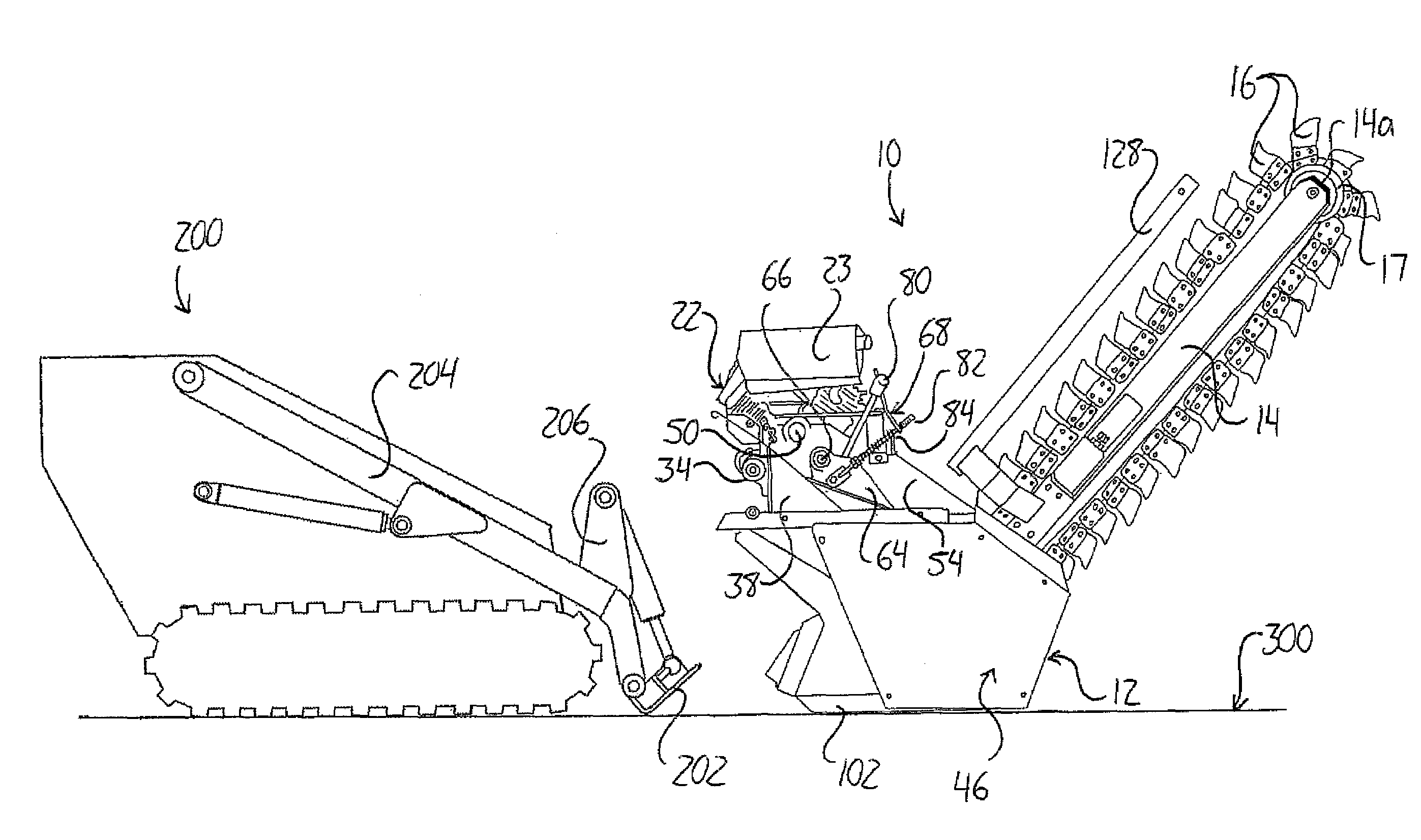
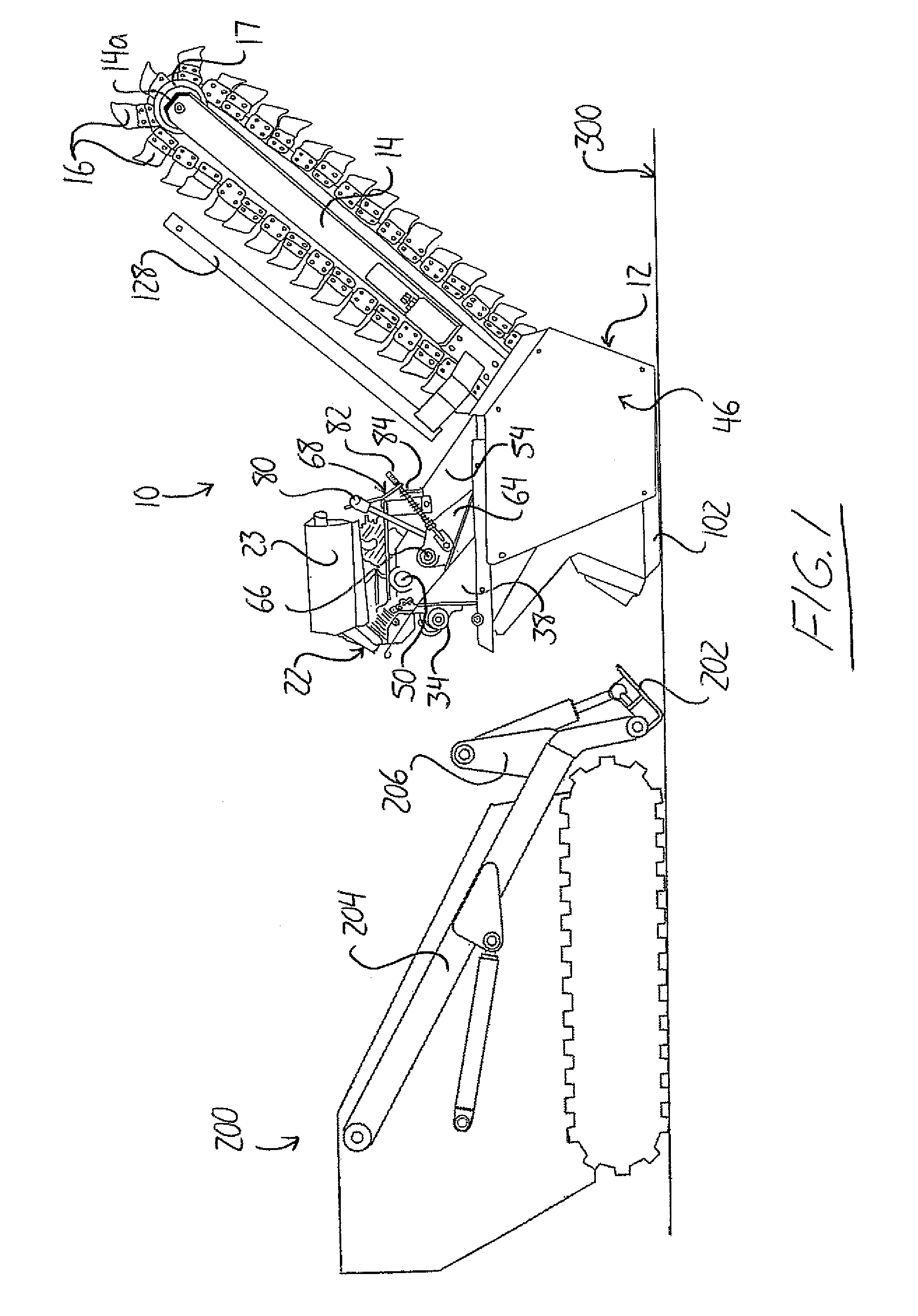
[0041]FIG. 1 shows a trenching attachment 10 adapted for removable mounting on the lift arms of an existing conventional walk-behind skid steer 200. The trenching attachment 10 feature a rigid frame 12 on which a boom arm 14 is pivotally mounted to facilitate swinging of a distal end 14a of the boom arm opposite the connection thereof to the frame 12 within a vertical plane with the frame 12 resting on a horizontal ground surface 300. An endless trenching or digging chain 15 featuring a plurality of cutting or digging blades or teeth 16 projecting outward therefrom is entrained about an idler sprocket 17 mounted for rotation about a horizontal axis at the distal end 14a of the boom arm 14 and about a drive sprocket mounted proximate the opposite end of the boom arm 14 connected to the frame 12 for rotation about a respective horizontal axis. As seen in FIG. 7, the mounting of the boom 14 at a front end of the attachment 10 is of a conventional structure known to those of skill in th...


PUM


Abstract

A trenching attachment for selective attachment to a working machine features a frame arranged for selective connection to the working machine, an internal combustion engine mounted to the frame and a boom assembly connected to the frame and having a trencher chain installed thereon. The internal combustion engine is operatively connected to the trenching chain to facilitate driving thereof. Having its own dedicated engine, the trenching attachment is less dependent on the power take-off system of the working machine than a conventional trenching attachment that uses a hydraulic motor to power the trencher chain and relies exclusively on delivery of hydraulic fluid from the working machine for operation.

Description

FIELD OF THE INVENTION[0001]This invention relates generally to trenchers, and more particularly to trenching attachments arranged for selective attachment to a work machine for cooperative use of the work machine and the trenching attachment as a self-propelled trencher.BACKGROUND OF THE INVENTION[0002]Trenching machines are commonly employed to form a trench or ditch recessed into the ground for the purpose of laying underground pipe or cable that can be subsequently buried by refilling the trench above the laid pipe or cable with the soil or ground material originally removed by such a machine. Conventionally, a trencher uses an endless chain that is equipped with teeth or blades and entrained around a drive sprocket and an idler sprocket carried at opposite ends of a boom arm that is pivotally mounted to a frame of the trencher to swing a distal end of the boom arm upward and downward within a vertical plane. With the chain being driven along the periphery of the boom around the...

Claims


Application Information

Patent Timeline
Patent Type & Authority Patents(United States)
IPC IPC(8): E02F5/04
CPCE02F3/12E02F5/06
Inventor BLACK, ALLAN
Owner BLACK ALLAN
Why Eureka
Try Eureka