Supercharge Your Innovation With Domain-Expert AI Agents!

Image heating apparatus and method for manufacturing image heating apparatus

Active Publication Date: 2010-02-02
CANON KK
View PDF11 Cites 11 Cited by
  • Summary
  • Abstract
  • Description
  • Claims
  • Application Information

AI Technical Summary

Benefits of technology

This configuration enhances the accuracy and stability of the heat roller and coil positioning, improving energy efficiency and reducing the time required to reach the desired temperature for image fixation, while minimizing the risk of overheating.

Problems solved by technology

According to the prior art, however, the position of the fixation roller is set independently from that of the coil, which has been problematic from the perspective of the level of accuracy at which the fixation roller and coil are positioned relative to each other.
With the fixation roller and coil not correctly positioned relative to each other, there is the possibility that if the coil and / or fixation roller deforms due to its own weight and / or the heat of the fixation roller, the coil and fixation will come into contact with each other.

Method used


Image

  • Image heating apparatus and method for manufacturing image heating apparatus
  • Image heating apparatus and method for manufacturing image heating apparatus
  • Image heating apparatus and method for manufacturing image heating apparatus

Examples


embodiment 1

(1) Example of Image Forming Apparatus

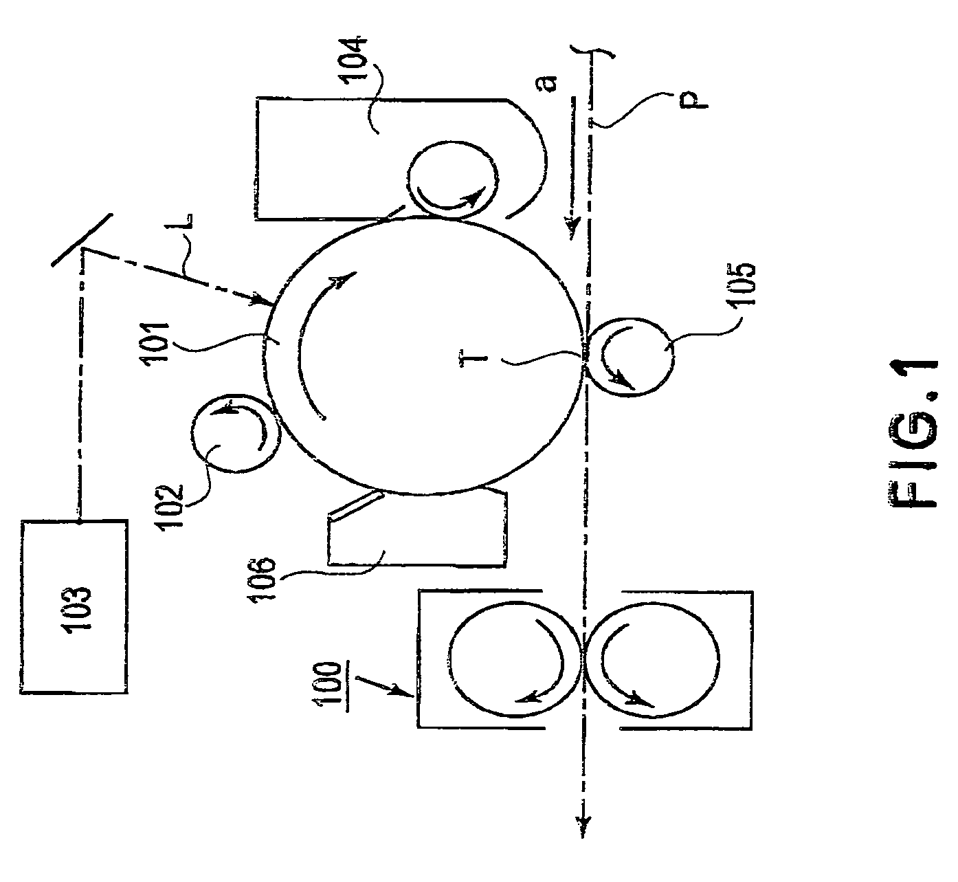
[0028]Hereinafter, the image heating apparatus, as a fixing apparatus, in accordance with the present invention will be described. First, referring to FIG. 1, the image forming apparatus in which this fixing apparatus is disposed will be described before the fixing apparatus is described. The image forming apparatus in this embodiment is a laser beam printer, which uses one of the electrophotographic processes.

[0029]Designated by referential symbols 101 is an electrophotographic photosensitive member (which hereinafter will be referred to simply as photosensitive drum), which is rotationally driven in the clockwise direction indicated by an arrow mark, at a preset peripheral velocity.

[0030]Designated by a referential symbol 102 is a charge roller, as a charging means, of the contact type, which uniformly charges the peripheral surface of the photosensitive drum 101 to preset polarity and potential level as the photosensitive drum 101 is rotated....


PUM

PropertyMeasurementUnit
cylindrical shapeaaaaaaaaaa
magnetic fluxaaaaaaaaaa
energy efficiencyaaaaaaaaaa

Abstract

An image heating apparatus includes a heating roller for heating an image on a recording material; a coil unit disposed in said heating roller and including a coil for induction heat generation in said heating roller; a supporting member for rotatably supporting said heating roller, wherein said supporting member including a holding portion for substantially non-rotatably holding said coil unit.

Description

FIELD OF THE INVENTION AND RELATED ART[0001]The present invention relates to an image heating apparatus for heating an image on recording medium, and the method for manufacturing such an image heating apparatus.[0002]There is disclosed a fixing apparatus employing one of the heating methods based on electromagnetic induction in Japanese Laid-open Patent Application 10-74009. A typical fixing apparatus of this type comprises a fixation roller and a coil. The fixation roller is heated by the eddy current which is induced in the wall of the fixation roller as the fixation roller is subjected to the magnetic flux generated by the coil. Thus, a fixing apparatus of this type is considered to be advantageous in terms of energy efficiency.[0003]A typical fixing apparatus employing a heating method based on electromagnetic induction (which hereinafter may be referred to simply as inductive fixing apparatus) comprises a fixation roller and a coil, which are physically independent from each ot...

Claims


Application Information

Patent Timeline
Patent Type & Authority Patents(United States)
IPC IPC(8): G03G15/20
CPCG03G15/2053
Inventor WAKAHARA, SHINICHIROWATANABE, KOKISHIRAKATA, JIROTAKEMATSU, KOJI
Owner CANON KK
Features
  • R&D
  • Intellectual Property
  • Life Sciences
  • Materials
  • Tech Scout
  • Unparalleled Data Quality
  • Higher Quality Content
  • 60% Fewer Hallucinations
Learn More