Bicycle rear derailleur

a rear derailleur and bicycle technology, applied in mechanical equipment, transportation and packaging, gearing, etc., can solve the problems of unsatisfactory shifting conditions, unsatisfactory shifting conditions, and inability to achieve optimal shifting conditions

Inactive Publication Date: 2010-02-23
SHIMANO INC
View PDF23 Cites 18 Cited by
  • Summary
  • Abstract
  • Description
  • Claims
  • Application Information

AI Technical Summary

Benefits of technology

[0010]Another object of the present invention is to provide a rear derailleur with a guide pulley that operates with minimal variations in distances from respective gears in a gear sprocket set.

Problems solved by technology

Unfortunately, the geometry of gear derailleurs and gear sprocket sets is such that the first, second and third distances are not equal and may differ undesirably.
Therefore, optimal shifting conditions are not being achieved.

Method used


Image

  • Bicycle rear derailleur
  • Bicycle rear derailleur
  • Bicycle rear derailleur

Examples


Embodiment Construction

[0031]Selected embodiments of the present invention will now be explained with reference to the drawings. It will be apparent to those skilled in the art from this disclosure that the following descriptions of the embodiments of the present invention are provided for illustration only and not for the purpose of limiting the invention as defined by the appended claims and their equivalents.

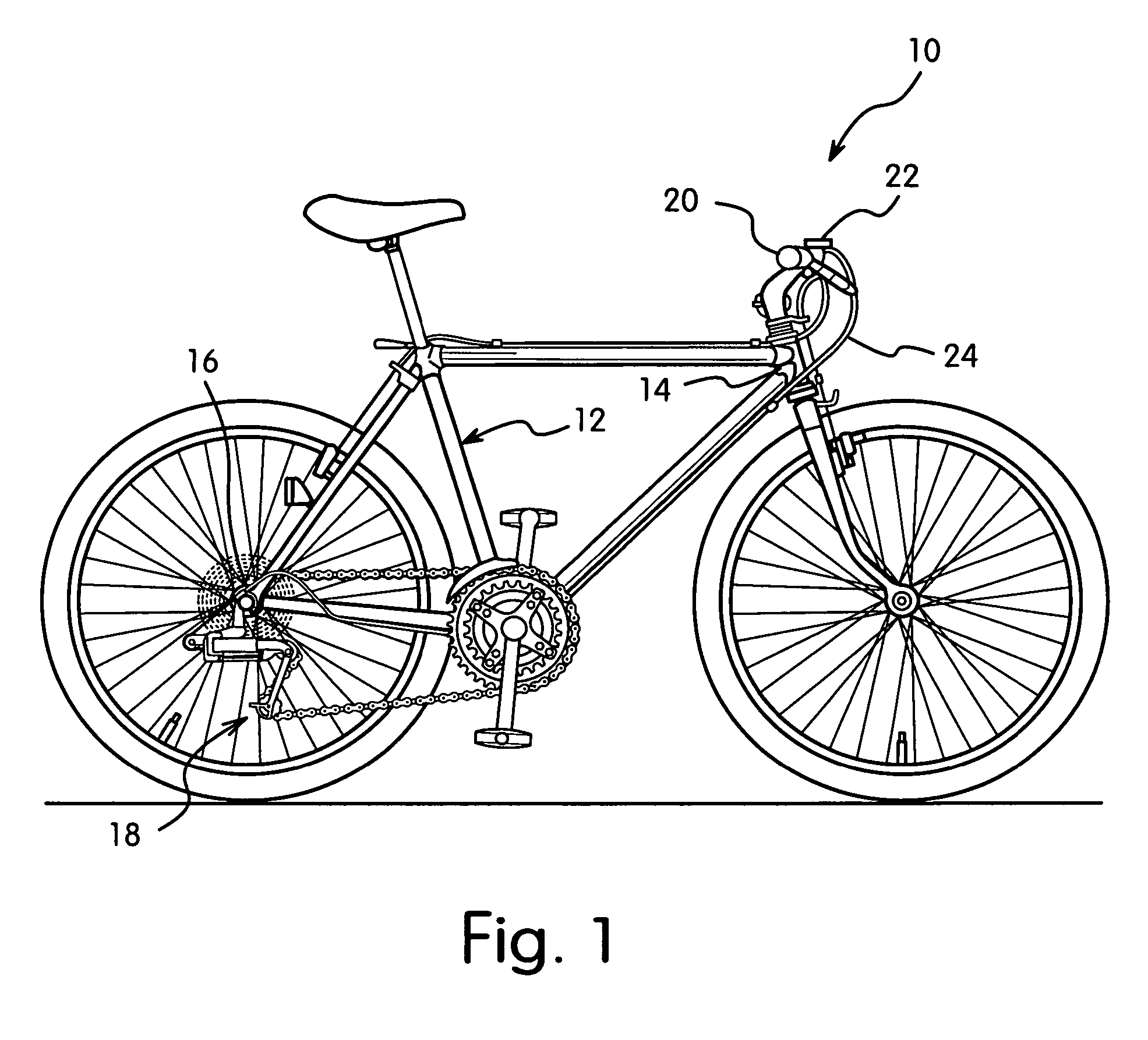
[0032]Referring initially to FIG. 1, a bicycle 10 is illustrated in accordance with a first embodiment of the present invention. The bicycle 10 includes a frame 12 that has a front end 14 and a rear end 16. A rear derailleur 18 in accordance with the present invention is mounted to the rear end 16 of the frame 12, as described in greater detail below.

[0033]The front end 14 of the frame 12 is coupled to and supports a handlebar 20. A gear shifting mechanism 22 is mounted to the handlebar 20. The gear shifting mechanism 22 operates in a conventional manner to control movement of the rear derailleur 1...


PUM


Abstract

A bicycle rear derailleur includes a base portion, a coupling mechanism, a moveable member, a pivot shaft, a tension plate, a biasing spring and a guide plate. The base portion attaches to a bicycle frame. The coupling mechanism has first and second ends. The first end is coupled to the base portion and the second end is movable relative to the base portion. The movable member is coupled to the second end and the pivot shaft is coupled to the movable member. The tension plate is pivotally coupled to the movable member by the pivot shaft and supports a chain tensioning pulley. The biasing spring is operatively coupled to the movable member and the tension plate for biasing the tension plate in a chain tensioning direction. The guide plate is pivotally coupled to the pivot shaft in a non-biased manner and supports a chain guiding pulley.

Description

BACKGROUND OF THE INVENTION[0001]1. Field of the Invention[0002]This invention generally relates to a bicycle rear derailleur. More specifically, the present invention relates to a bicycle rear derailleur having a tension plate that supports a chain tensioning pulley and a guide plate that supports a chain guiding pulley where the guide plate and tension plate are mounted to a pivot shaft with independent pivotal movement with respect to one another.[0003]2. Background Information[0004]Bicycling is becoming an increasingly more popular form of recreation as well as a means of transportation. Moreover, bicycling has become a very popular competitive sport for both amateurs and professionals. Whether the bicycle is used for recreation, transportation or competition, the bicycle industry is constantly improving the various components of the bicycle. One component that has been extensively redesigned is the bicycle rear derailleur.[0005]Rear derailleurs are well known and typically incl...

Claims


Application Information

Patent Timeline
Patent Type & Authority Patents(United States)
IPC IPC(8): F16H63/00F16H9/00B62M9/125B62M9/126B62M9/127
CPCB62M9/125B62M9/16
Inventor SHAHANA, SATOSHIYAMAGUCHI, SOUTA
Owner SHIMANO INC
Why Eureka
Try Eureka