
System and method for position control of a mechanical piston in a pump

a mechanical piston and pump technology, applied in the field of fluid pumps, can solve the problems of high cost of photochemicals used in the semiconductor industry today, the pressure can vary from system to system, and the desirable qualities can be extremely difficult to achieve in today's pumping systems, so as to achieve precise and repeatable position control of fluid movement, reduce heat generation, and enhance speed control

Active Publication Date: 2012-03-22
ENTEGRIS INC
View PDF1 Cites 14 Cited by
  • Summary
  • Abstract
  • Description
  • Claims
  • Application Information

AI Technical Summary

Benefits of technology

The system achieves real-time, smooth motion with precise and repeatable control over fluid movements and dispense amounts, minimizing pressure spikes and fluid damage, while optimizing energy use and extending the operational range of the pumping system.

Problems solved by technology

Photochemicals used in the semiconductor industry today are typically very expensive, costing as much as $1000 and up per a liter.
Unfortunately, these desirable qualities can be extremely difficult to achieve in today's pumping systems because of the many interrelated obstacles.
For example, due to incoming supply issues, pressure can vary from system to system.
In operation, vibration from various parts of a pumping system (e.g., a stepper motor) may adversely affect the performance of the pumping system, particularly in the dispensing phase.
In pumping systems utilizing pneumatic pumps, when the solenoid comes on, it can cause large pressure spikes.
In pumping systems utilizing multiple stage pumps, a small glitch in operation can also cause sharp pressure spikes in the liquid.
Such pressure spikes and subsequent drops in pressure may be damaging to the fluid (i.e., may change the physical characteristics of the fluid unfavorably).
Additionally, pressure spikes can lead to build up fluid pressure that may cause a dispense pump to dispense more fluid than intended or dispense the fluid in a manner that has unfavorable dynamics.
Furthermore, because these obstacles are interrelated, sometimes solving one may cause many more problems and / or make the matter worse.
Generally, pumping systems are unable to satisfactorily control pressure variation during a cycle.

Method used


Image

  • System and method for position control of a mechanical piston in a pump
  • System and method for position control of a mechanical piston in a pump
  • System and method for position control of a mechanical piston in a pump

Examples


Embodiment Construction

[0026]Preferred embodiments of the invention are described below with reference to the figures which are not necessarily drawn to scale and where like numerals are used to refer to like and corresponding parts of the various drawings.

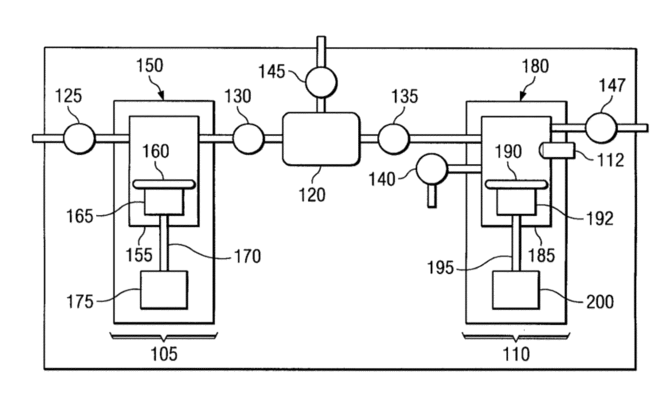
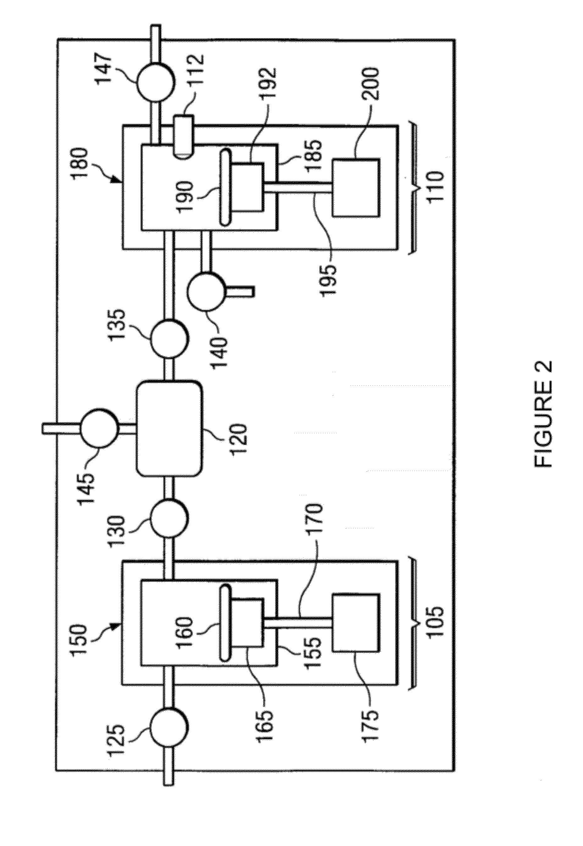
[0027]Embodiments of the invention are directed to a pumping system with a multiple stage (“multi-stage”) pump for feeding and dispensing fluid onto wafers during semiconductor manufacturing. Specifically, embodiments of the invention provide a pumping system implementing a multi-stage pump comprising a feed stage pump driven by a stepper motor and a dispense stage pump driven by a brushless DC motor for extremely accurate and repeatable control over fluid movements and dispense amounts of the fluid onto wafers. It should be noted that the multi-stage pump and the pumping system embodying such a pump as described herein are provided by way of example, but not limitation, and embodiments of the invention can be implemented for other multi-stage pump conf...


PUM


Abstract

Embodiments of the systems and methods disclosed herein utilize a brushless DC motor (BLDCM) to drive a single-stage or a multi-stage pump in a pumping system for real time, smooth motion, and extremely precise and repeatable position control over fluid movements and dispense amounts, useful in semiconductor manufacturing. The BLDCM may employ a position sensor for real time position feedback to a processor executing a custom field-oriented control scheme. Embodiments of the invention can reduce heat generation without undesirably compromising the precise position control of the dispense pump by increasing and decreasing, via a custom control scheme, the operating frequency of the BLDCM according to the criticality of the underlying function(s). The control scheme can run the BLDCM at very low speeds while maintaining a constant velocity, which enables the pumping system to operate in a wide range of speeds with minimal variation, substantially increasing dispense performance and operation capabilities.

Description

CROSS-REFERENCE TO RELATED APPLICATIONS[0001]This is a divisional application of U.S. patent application Ser. No. 11 / 602,485, filed Nov. 20, 2006, now allowed, entitled “SYSTEM AND METHOD FOR POSITION CONTROL OF A MECHANICAL PISTON IN A PUMP,” which claims priority from U.S. Provisional Patent Application Nos. 60 / 741,660, filed Dec. 2, 2005, entitled “SYSTEM AND METHOD FOR POSITION CONTROL OF A MECHANICAL PISTON IN A PUMP” and 60 / 841,725, filed Sep. 1, 2006, entitled “SYSTEM AND METHOD FOR POSITION CONTROL OF A MECHANICAL PISTON IN A PUMP.” all of which are incorporated herein by reference for all purposes.TECHNICAL FIELD OF THE INVENTION[0002]This invention relates generally to fluid pumps. More particularly, embodiments of the invention relate to system and method for position control of a mechanical piston in a motor-driven single-stage or multi-stage pump useful in semiconductor manufacturing.BACKGROUND OF THE INVENTION[0003]There are many applications for which precise control ...

Claims


Application Information

Patent Timeline
Patent Type & Authority Applications(United States)
IPC IPC(8): F04B49/06
CPCF04B25/00F04B17/03Y10S417/90F04B49/065
Inventor GONNELLA, GEORGECEDRONE, JAMESGASHGAEE, IRAJ
Owner ENTEGRIS INC
Learn More