Antenna device and multi-band type wireless communication apparatus using same

a multi-band wireless communication and antenna technology, applied in the direction of resonant antennas, elongated active elements, shielding material radiating elements, etc., can solve the problems of narrow bandwidth, lowered radiation efficiency, difficult fine adjustments, etc., to maintain the non-directivity of vertically polarized waves, improve the degree of freedom of layout, and excellent gain

Inactive Publication Date: 2010-03-16
HITACHI METALS LTD
View PDF12 Cites 15 Cited by
  • Summary
  • Abstract
  • Description
  • Claims
  • Application Information

AI Technical Summary

Benefits of technology

[0007]In view of the above, it is an object of the present invention to provide technology capable of realizing an antenna device that can operate in wide bands (in a multi-band) and can achieve an excellent antenna gain and maintain non-directivity of vertically polarized waves in each band in a space-saving manner.
[0008]As a result from various studies and researches of smaller-sized antenna devices, the inventor of the present invention has invented the antenna device which can save more space compared with the conventional antenna device and also can perform operation in wide bands (in a plurality of frequency bands) and can achieve excellent antenna gain and maintain non-directivity of vertically polarized waves in each band, that is, in order to solve the above problems, there is provided an antenna device made up of an approximately U-shaped conductor antenna, on one end side of which a power feeding portion is provided and on other end side of which an end portion is provided as an open end terminal and a base body made of an insulating material, wherein one end of the conductor antenna and other end of the conductor antenna are placed so as to come near to each other with the base body interposed between the one end of the conductor and the other end of the conductor antenna and wherein the base body is coupled to at least either of the one end side of the conductor or the other end side of the conductor antenna.
[0009]By configuring as above, one end and the other end of the U-shaped conductor antenna are placed so as to come near to each other and the base body made of an insulating material is mounted between the one end and the other end of the U-shaped conductor antenna and is coupled to at least either of the one end or the other end portion. That is, the base body made of a dielectric material or magnetic material both being an insulating material is coupled to a place where an electric field strength of the conductor antenna increases and, as a result, an electromagnetic distance between the one end and the other end of the conductor antenna becomes short to a degree to which electrostatic coupling occurs, which allows a resonant point to be easily obtained and, therefore, the antenna can be miniaturized by a wavelength shortening effect of the dielectric or magnetic material being the insulating material. Therefore, the antenna device is allowed to operate in wide bands (in a multi-band) and to achieve excellent antenna gain and maintain non-directivity of vertically polarized waves and save space. Particularly, the above antenna device has the flexibility of easily achieving wide-band operations in a plurality of frequency bands. It is thus made possible to realize excellent gain and to keep non-directivity of vertically polarized waves in wider bands (in a plurality of bands). Moreover, in each band, excellent antenna gain can be obtained and non-directivity of vertically polarized waves is kept in wider bands.

Problems solved by technology

However, the conventional antenna devices disclosed in the Patent References 1 and 2 have a problem in that fine adjustments are not easy since their impedance matching is performed by using the radiation electrode patterns formed on the dielectric antenna portion.
The antenna device disclosed in the Patent Reference 3 has also a problem in that a bandwidth is made narrow and radiation efficiency is lowered since the dielectric is placed between the radiation conductor and a grounding conductor.
The antenna device disclosed in the Patent Reference 4 has also a problem in that the radiation efficiency and sensitivity are lowered when compared with the antenna devices disclosed in the Patent References 1, 2, and 3.
The antenna device disclosed in the Patent Reference 4 has another problem that an antenna needs to be installed for every band and space for the antenna device is greatly occupied by antenna circuits and its antenna gain is reduced due to fluctuations of directivity of the antenna and degradation in VSWR (Voltage Standing Wave Ratio) caused by interactions among the installed antennas for each band.
The antenna device disclosed in the Patent Reference 5 has a problem that the antenna used is a single loop antenna in which its line length or electrical length consists of one wavelength and, therefore, space for the antenna is greatly occupied in the antenna device.

Method used


Image

  • Antenna device and multi-band type wireless communication apparatus using same
  • Antenna device and multi-band type wireless communication apparatus using same
  • Antenna device and multi-band type wireless communication apparatus using same

Examples


first embodiment

[0080]FIG. 3 is a graph showing a relation between VSWR (Voltage Standing Wave Ratio) and frequency in the antenna device 100 of the The VSWR is a value expressing a degree of reflection of power transmitted to the antenna device 100. The smaller the value is (the nearer to 1), the better and the effective the transmission of applied power to the antenna device 100 is and the less the reflection of the power is. The smaller value represents that the antenna property is excellent. Preferably, the VSWR is 5.00 or less in a frequency band to be used. FIG. 3 shows apparently that satisfactory antenna properties were obtained in a frequency band (860 MHz to 1100 MHz) being near to the GSM band (900 MHz band), and in a frequency band (1600 MHz to 1900 MHz) being near to the DCS (1700 MHz band) and the PCS (1800 MHz band) band and in a frequency band (2050 MHz to 2200 MHz) being near to the UMTS.

[0081]FIG. 4 is a graph showing a relation between radiation efficiency and frequency in the a...

second embodiment

[0083]FIG. 6 is a graph showing a relation between VSWR and frequency in the antenna device 200 shown in FIG. 5 according to the Preferably, the VSWR is 5. 00 in a frequency band to be used. As is apparent from FIG. 6, satisfactory antenna properties were obtained in a frequency band (860 MHz to 1100 MHz) being near to the GSM (900 MHz) band, and in a frequency band (1600 MHz to 1900 MHz) being near to the DCS (1700 MHz) and the PCS (1800 MHz) bands and in a frequency band (2050 MHz to 2200 MHz) being near to the UMTS (2200 MHz) band.

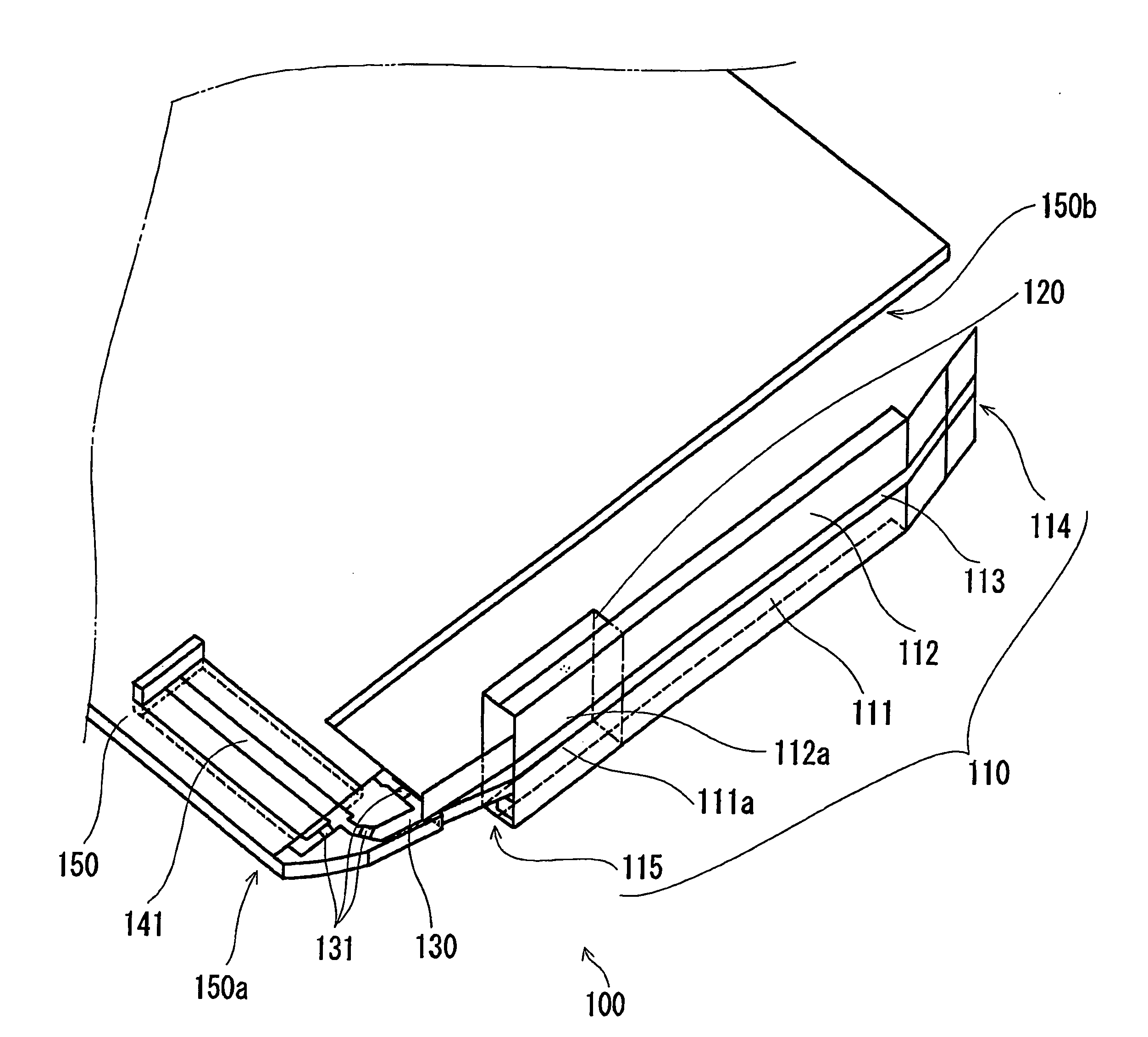
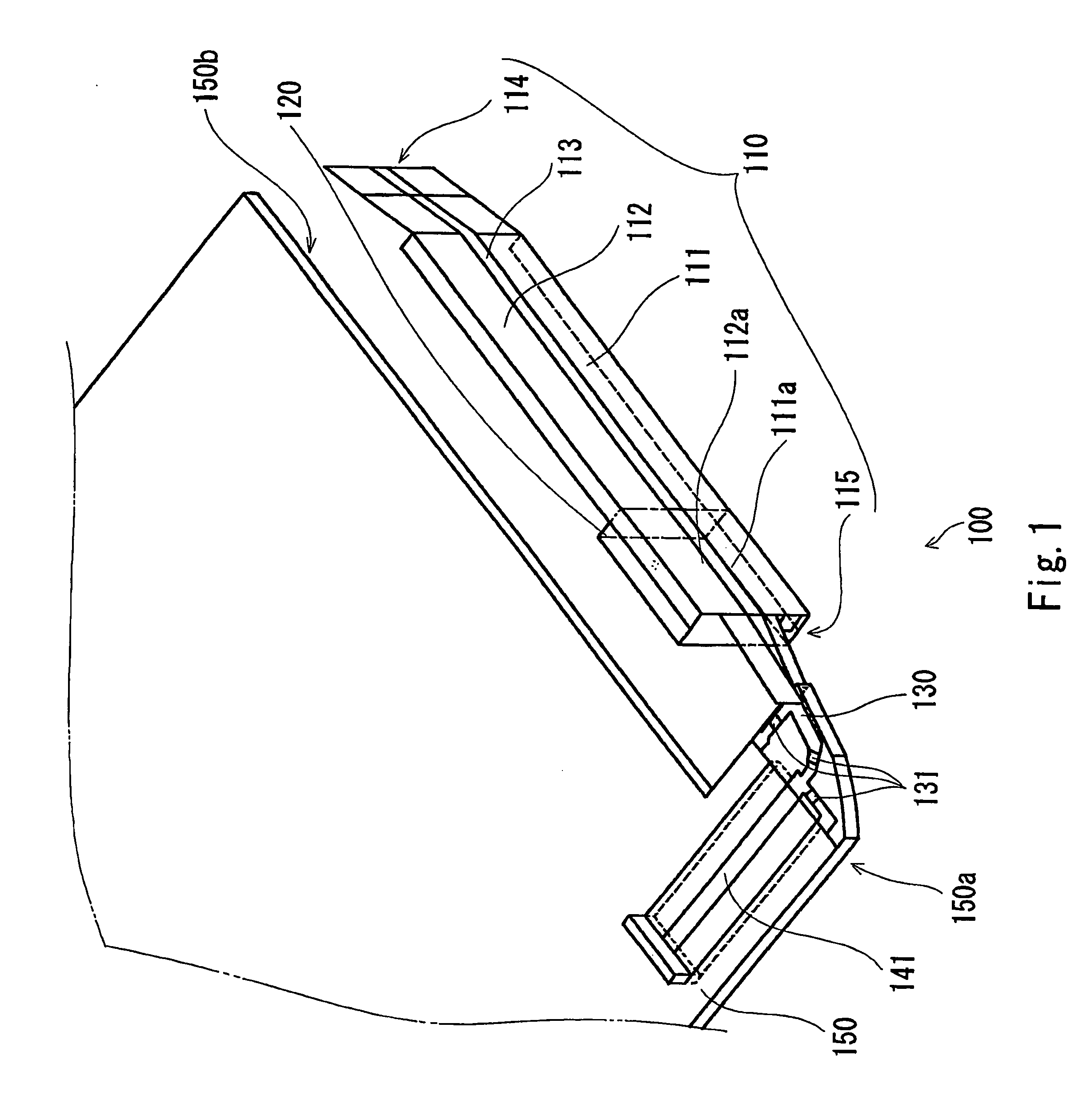
[0084]Next, an antenna device of the third embodiment of the present invention is described by referring to FIGS. 7 and 8. FIG. 7 is a diagram showing basic configurations of the antenna device 300 of the third embodiment of the present invention, which is shown in a manner to correspond to FIG. 1. In FIG. 7, same reference numbers are assigned to components corresponding to those in FIG. 1 and their descriptions are omitted accordingly. In the antenna...

sixth embodiment

[0102]Moreover, in the sixth embodiment, the conductor 612 on the other end side of the conductor antenna 610 is formed by sticking foil to the rear surface 640B, however, as in the case of the conductor 611 on the one end side, the conductor 612 may be formed by using a metal plate made of bronze phosphate. In this case, the conductor 612 may be formed by sticking a plane portion of the metal plate on the rear surface 640B. Also, the conductor 612 on the other end side of the conductor antenna 610 is made up of a metal plate and the conductor 611 may be formed by combining other materials, for example, by using a line material (metal conductive line) or a like. In this case, both the conductors 612 and 611 may be coupled via a through-hole electrode or may be electrically connected via a side face electrode formed on a side face of the board serving as a folded-back portion.

[0103]Thus, in the antenna device 600 of the sixth embodiment, the end portion 612 of the conductor 612 on th...


PUM


Abstract

An antenna device is provided which is capable of saving space, of operating in wide bands (in a multi-band) and of achieving an excellent gain and maintaining non-directivity of vertically polarized waves in each band. The antenna device has a conductor antenna. An end portion 111a on one end side of the conductor antenna is mounted as a power feeding section and an end portion 112a on the other end side of the conductor antenna 110 is mounted as an open end terminal. The antenna device also has a base body made of an insulating material which is coupled to one end and other end of the conductor antenna. The base band is coupled in a place where an electric field strength of the conductor antenna having a folded-back portion is increased, thus achieving the wideband and high-gain antenna device.

Description

BACKGROUND OF THE INVENTION[0001]1. Field of the Invention[0002]The present invention relates to an antenna device and more particularly to the antenna device that can operate in a plurality of bands (transmitting / receiving bands) and a multi-band wireless communication apparatus using the antenna device.[0003]2. Description of the Related Art[0004]In recent years, a wireless communication apparatus such as a mobile phone or a like has become widespread and various bands are used in communications. In a recently-available mobile phone called a dual-band, triple-band, or quad-band type mobile phone in particular, one mobile phone is made to operate in a plurality of bands (transmitting / receiving bands). In such a circumstance, hurried development of an antenna device making up antenna circuits that can be embedded in a mobile phone or a like being capable of operating in a plurality of bands (transmitting / receiving bands) described above is needed. It is thus necessary that, in order...

Claims


Application Information

Patent Timeline
Patent Type & Authority Patents(United States)
IPC IPC(8): H01Q1/24H01Q5/371
CPCH01Q1/243H01Q1/36H01Q5/371H01Q9/42H01Q1/38H01Q1/24
Inventor TAKAKI, YASUNORIAOYAMA, HIROYUKIIDENO, HIROTO
Owner HITACHI METALS LTD
Why Eureka
Try Eureka