Plastic fasteners, needles for dispensing and method of manufacture

a technology of plastic fasteners and needles, applied in the direction of identification means, instruments, seals, etc., can solve the problems of undesirable results, inability to achieve the proper engagement of the cross-bar by the ejector rod and the proper translational movement of the cross-bar through the length of the bore due to the action of the ejector rod, and the failure of the tool to work properly

Inactive Publication Date: 2010-03-23
AVERY DENNISON CORP
View PDF15 Cites 9 Cited by
  • Summary
  • Abstract
  • Description
  • Claims
  • Application Information

AI Technical Summary

Benefits of technology

[0021]It should be readily understood that, by selecting an appropriately shaped master, one can adapt the above-described needle fabrication method to make a needle particularly well-suited for use with a fastener whose filament and cross-bar have a coplan

Problems solved by technology

One problem that has been noted by the present inventor with respect to the dispensing of continuously connected fastener stock of the type described above using needles of the type described above is that, whereas the longitudinal bore and the longitudinal slot together have a symmetric transverse cross-sectional shape resembling an inverse lollipop (the longitudinal bore being circular in transverse cross-section, the longitudinal slot being rectangular in transverse cross-section and bisecting said longitudinal bore at the top thereof), the first cross-bar and the

Method used


Image

  • Plastic fasteners, needles for dispensing and method of manufacture
  • Plastic fasteners, needles for dispensing and method of manufacture
  • Plastic fasteners, needles for dispensing and method of manufacture

Examples


first embodiment

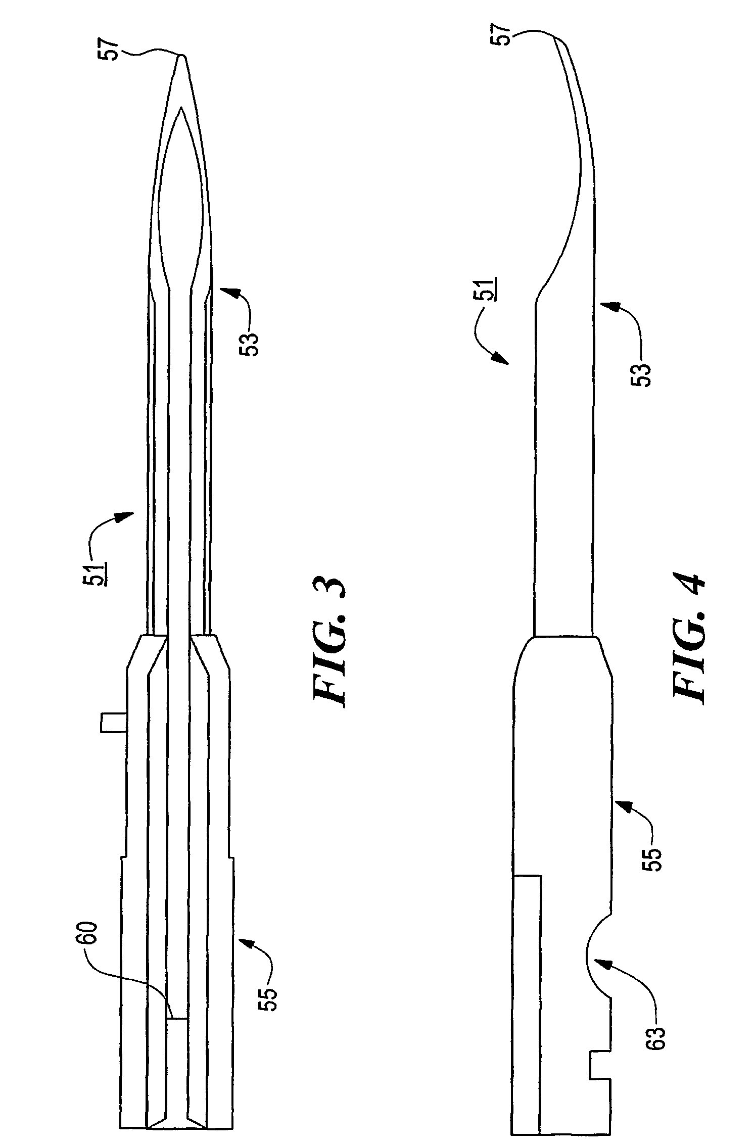
[0062]Referring now to FIG. 7, there is shown a left side view of a needle constructed according to the teachings of the present invention, the needle being represented generally by reference numeral 101.

[0063]Needle 101 comprises a stem portion 103 and a base portion 105. Base portion 105, which is identical in all respects to base portion 55, may be made by insert-molding plastic onto the rear end of stem portion 103.

[0064]Stem portion 103 is similar in certain respects to stem portion 53. For example, stem portion 103 is an elongated member terminating at its front end in a spoon-shaped tip 107, tip 107 being sufficiently sharp to enable its penetration into a desired article of commerce. However, as shown in FIG. 8, stem portion 103 differs markedly from stem portion 53 in that stem portion 103 has a generally “d”-shaped transverse cross-section, instead of the generally annular transverse cross-section of stem portion 53. As such, stem portion 103 defines a generally semi-ellip...

second embodiment

[0067]Referring now to FIG. 9, there is shown a transverse section view of a stem portion of a needle constructed according to the teachings of the present invention, the stem portion being represented generally by reference numeral 151.

[0068]Stem portion 151 is identical in virtually all respects to stem portion 103, the principal difference between stem portion 151 and stem portion 103 being that stem portion 151 is shaped to define a generally rectangular bore 153, instead of the generally semi-elliptical bore 109 of stem portion 103. Bore 153 has a transverse cross-sectional height h1 and a transverse cross-sectional width w3, height h1 being greater than width w3 and extending parallel to the length of a filament in slot 155.

[0069]Stem portion 151 is preferably made in the same manner as stem portion 103, and a suitably shaped base portion (not shown) is preferably insert-molded onto the rear end of stem portion 151 in the conventional manner.

[0070]Because of the generally rect...

third embodiment

[0075]Referring now to FIG. 14, there is shown a fragmentary perspective view of a needle constructed according to the teachings of the present invention, said needle being represented generally by reference numeral 251.

[0076]Needle 251 comprises a stem portion 253 and a base portion (not shown), said base portion being similar to base portion 55 and preferably being made by insert-molding plastic onto the rear end of stem portion 253.

[0077]Stem portion 253 is similar in many respects to stem portion 103. For example, stem portion 253 is an elongated member terminating at its front end in a spoon-shaped tip 257, tip 257 being sufficiently sharp to enable its penetration into a desired article of commerce. However, as seen best in FIG. 15, stem portion 253 differs primarily from stem portion 103 in that stem portion 253 has a longitudinal bore 259 of a generally “B”-shaped transverse cross-section, instead of the generally semi-elliptical bore 109 of stem portion 103. Bore 259 is bou...


PUM


Abstract

A needle (51) particularly well-suited for use in the dispensing of plastic fasteners (21) of the type comprising a filament (15) having a cross-bar (23-1, 23-2) at a first end thereof, each of the cross-bar (23-1, 23-2) and the filament (15) including a first flat side, the first flat sides of the cross-bar (23-1, 23-2) being coplanar. The needle (51) includes a stem portion (53). The stem portion (53) terminates in a tip (57) at its front end and is shaped to define a longitudinal bore (59) and a longitudinal slot (61) for receiving the filament (15) and the cross-bar (23-1, 23-2). The longitudinal bore (59) has a first flat side, and the longitudinal slot (61) has a first flat side, wherein the flat sides are coplanar.

Description

CROSS-REFERENCE TO RELATED APPLICATIONS[0001]The present application is a continuation-in-part of U.S. patent application Ser. No. 09 / 740,700, filed Dec. 19, 2000, now U.S. Pat. No. 6,564,939 in the names of Charles L. Deschenes and Daniel Gilbertson, and is also a continuation-in-part of U.S. patent application Ser. No. 09 / 625,334, filed Jul. 25, 2000, in the name of Charles L. Deschenes, now U.S. Pat. No. 6,427,895.BACKGROUND OF THE INVENTION[0002]The present invention relates to the dispensing of plastic fasteners of the type that are used, for example, to attach tags to articles of commerce.[0003]Plastic fasteners of the type comprising an elongated flexible filament having a first cross-bar at one end and a second cross-bar (or other enlargement, such as a paddle or a knob) at the opposite end are well-known and have been widely used in a variety of applications, such as in the attachment of merchandise tags to articles of commerce, in the attachment of buttons to garments, in ...

Claims


Application Information

Patent Timeline
IPC IPC(8): B65D85/24B65C7/00G09F3/12
CPCB65C7/00B65C7/003G09F3/14Y10S206/82
Inventor COOPER, WILLIAM J.RAYMOND, JEFFREY A.DESCHENES, CHARLES L.GILBERTSON, DANIEL
Owner AVERY DENNISON CORP
Why Eureka
Try Eureka