Removable optical sight mount adapted for use with M14, M1A and similar rifles and method for removably attaching an optical sight to a rifle

a technology mount, which is applied in the field of removable attachment of optical or telescopic sight mount to a rifle, can solve the problems of not being able to easily use the modern m16/m4 attachment and accessories with the m1a or m14 pattern rifle, unable to meet the requirements of a telescopic mount of acceptable but not superior accuracy, and many of the same mounting problems were carried forward

Inactive Publication Date: 2010-04-13
KENG
View PDF16 Cites 50 Cited by
  • Summary
  • Abstract
  • Description
  • Claims
  • Application Information

AI Technical Summary

Benefits of technology

[0010]Accordingly, it is a primary object of the present invention to overcome the above mentioned difficulties by providing a removable and centrally aligned mount for optical sights having limited eye relief.
[0011]It is also an object of this invention to provide a removable mount that does not require gunsmithing or permanent modification of the rifle.
[0012]Another object is to provide a removable mount adapted for use on a rifle having a rolling block action that can be installed by a user, removed, and then re-installed without causing a substantial change to the zero or aim point adjustment of the optical sight.

Problems solved by technology

Unfortunately, many of the modern M16 / M4 attachments and accessories are not readily used with an M1A or M14 pattern rifle, since those rifles were originally configured for use solely with iron or mechanical sights.
The heat treating process associated with drilling and tapping the receiver (for the Griffin and Howe system) delayed production and so few M1Cs were delivered for combat service during W.W.II.
These expensive and protracted procedures resulted in a telescopic mount of acceptable but not superior accuracy.
When the M1A and M14 replaced the M1 Garand as the principal service rifle, many of the same mounting problems were also carried forward, since the newer rifles also used the rolling block action and receiver configuration.
This legacy now creates a number of new problems for armorers.
Contemporary users of the M14 and M1A have sought to use modern optical sighting systems including, for example, the Trijicon ACOG (i.e., “Advanced Combat Optical Gunsight”) optical sighting system, but there is not a practical way to releasably mount such modern optical devices to these older service rifles.

Method used


Image

  • Removable optical sight mount adapted for use with M14, M1A and similar rifles and method for removably attaching an optical sight to a rifle
  • Removable optical sight mount adapted for use with M14, M1A and similar rifles and method for removably attaching an optical sight to a rifle
  • Removable optical sight mount adapted for use with M14, M1A and similar rifles and method for removably attaching an optical sight to a rifle

Examples


Embodiment Construction

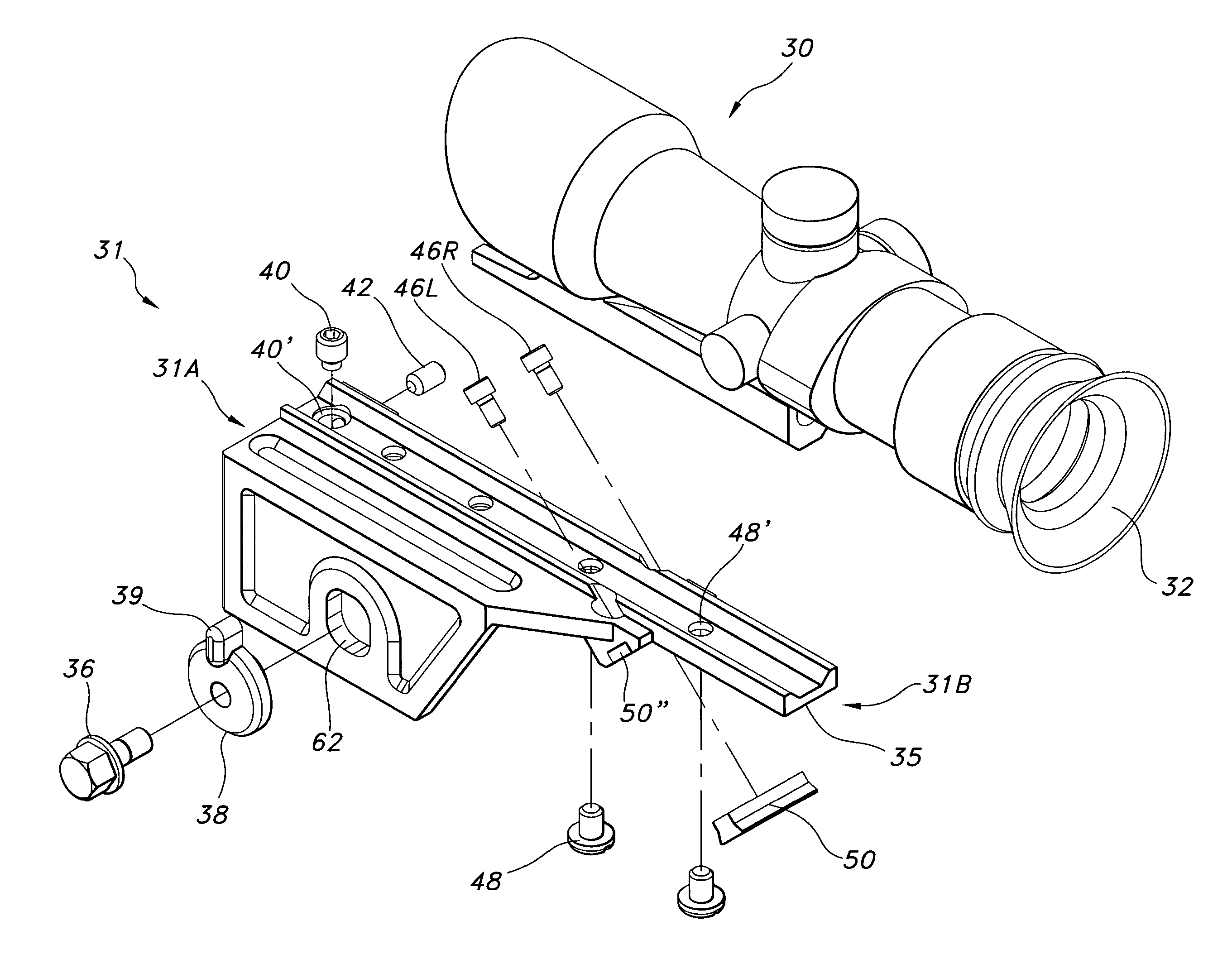
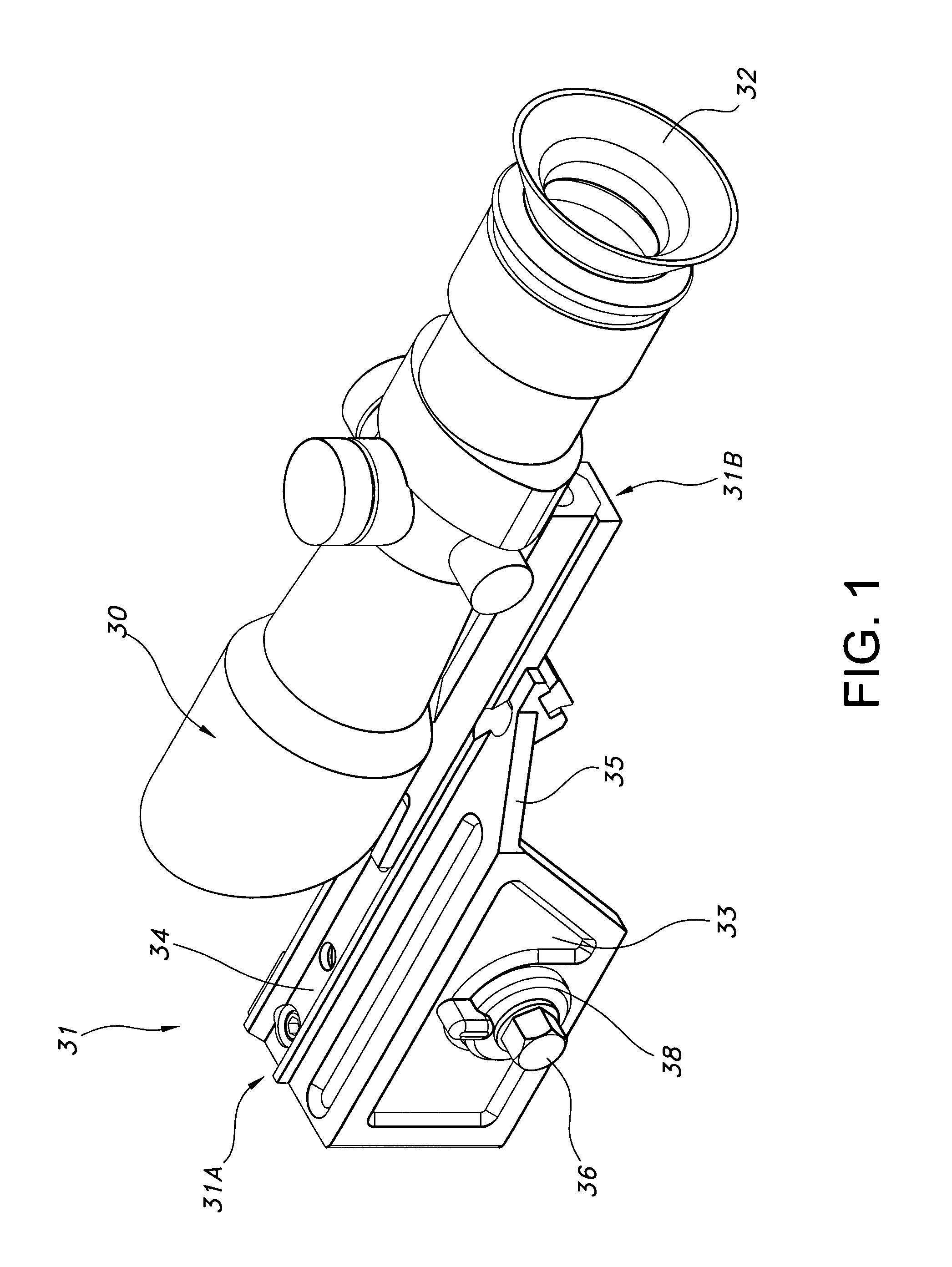
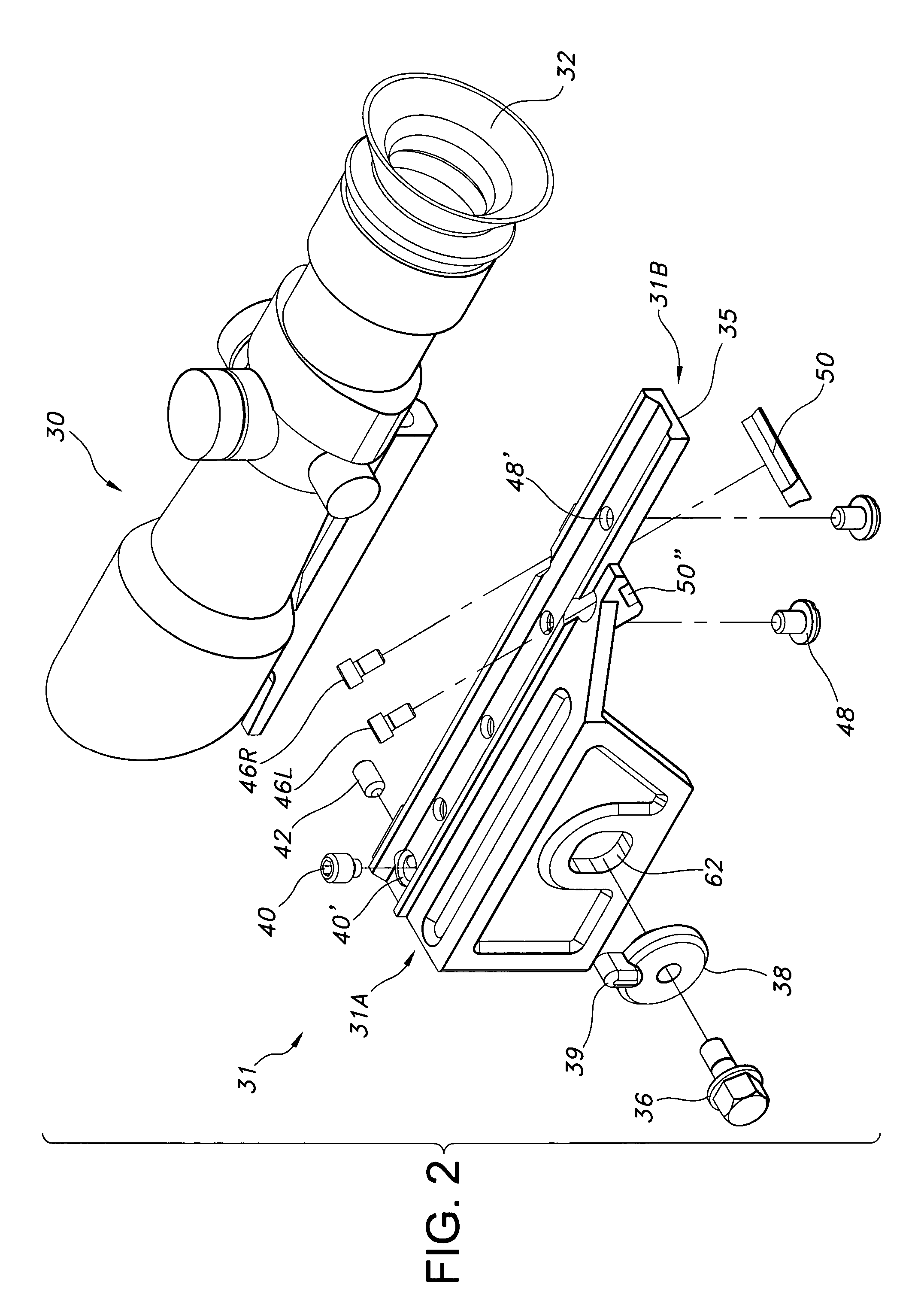
[0065]Referring to FIGS. 1 thru 17E, illustrating the mount apparatus 31 and method of the present invention, the mounting is advantageously set much further back or proximally towards the shooter's face and eyes. As noted above, a centrally aligned rearwardly projecting mounting surface 34 is necessary when using certain optical sights such as the ACOG 30 because of their very short eye relief (e.g., about 1.5 inches).

[0066]The removable mount 31 of the present invention places the ACOG's ocular lens 32 closer to the shooter's eye. The ACOG optical sighting device 30 has found a lot of favor recently because the shooter can keep both eyes open, providing a more natural way of aiming at live, human-size targets at close quarters in a real time situation where speed is everything. The removable mount 31 is intended to enhance that “both eyes open” rapid target acquisition characteristic that the ACOG sight offers, and so in order to mount the ACOG device closer to the shooter's face ...


PUM


Abstract

A removable optical sight mount adapted for use with a military-style rifle such as an M1A provides a centrally aligned support projecting well to the rear for use with sights having very limited eye relief. The removable sight advantageously uses a three point lock up or attachment to the rifle, the three points being (1) an elongated longitudinal tenon engaging a groove on the left side of the rifle secured with a fastener and cammed into tight engagement with the groove, (2) a transverse rear guide block, and (3) an adjustable front set screw that, when tightened, bears on the rifle receiver's crown.

Description

CROSS-REFERENCE TO RELATED APPLICATIONS[0001]This application claims priority, under 35 U.S.C. §119(e), to U.S. Provisional Application No. 60 / 771,020 filed Feb. 8, 2006, the entire contents of which are incorporated herein by reference.BACKGROUND OF THE INVENTION[0002]1. Field of the Invention[0003]The present invention relates to firearm sights and, more specifically, to a method and apparatus for removably attaching a mount for an optical or telescopic sight to a rifle.[0004]2. Discussion of the Prior Art[0005]Military and competition shooters have come to appreciate the simple construction and reliable operation of rifles having Garand-style rolling block operation. Such Rifles include the M1 Garand (in 30-06 caliber), the M1A (in .308 or 7.62 NATO caliber) and the select fire M14 (also in .308 or 7.62 NATO caliber).[0006]The M14 is still used for certain military applications, in part because of the significant power advantage provided by the .308 or 7.62 NATO caliber projectil...

Claims


Application Information

Patent Timeline
Patent Type & Authority Patents(United States)
IPC IPC(8): F41G1/38
CPCF41G11/003F41G1/387
Inventor KENG, DA
Owner KENG
Why Eureka
Try Eureka