Circuit for generating on-die termination control signal

Active Publication Date: 2010-04-13
SK HYNIX INC
View PDF18 Cites 5 Cited by
  • Summary
  • Abstract
  • Description
  • Claims
  • Application Information

AI Technical Summary

Benefits of technology

[0019]A circuit for generating an on-die termination control signal capable of preventing a control error when an on-die termination control is performed in an abnormal operation period, such as a refresh period is described herein, as is a circuit for generating an on-die termination control signal capable of preventing a control error caused by a collision between an on-die termina

Problems solved by technology

Since the voltage or the frequency is switched in the FVS period, the voltage or the frequency is unstable in the FVS period.
Since the voltage or the frequency is unstable in the FVS period, the toggling of the system stabilizing signal (RES) may occur.
However, a conventional circuit for generating the on-die termination control signal has the following problems: First, since the on-die termination control signal is generated in the self-

Method used


Image

  • Circuit for generating on-die termination control signal
  • Circuit for generating on-die termination control signal
  • Circuit for generating on-die termination control signal

Examples


Embodiment Construction

.”

BRIEF DESCRIPTION OF THE DRAWINGS

[0024]Features, aspects, and embodiments are described in conjunction with the attached drawings, in which:

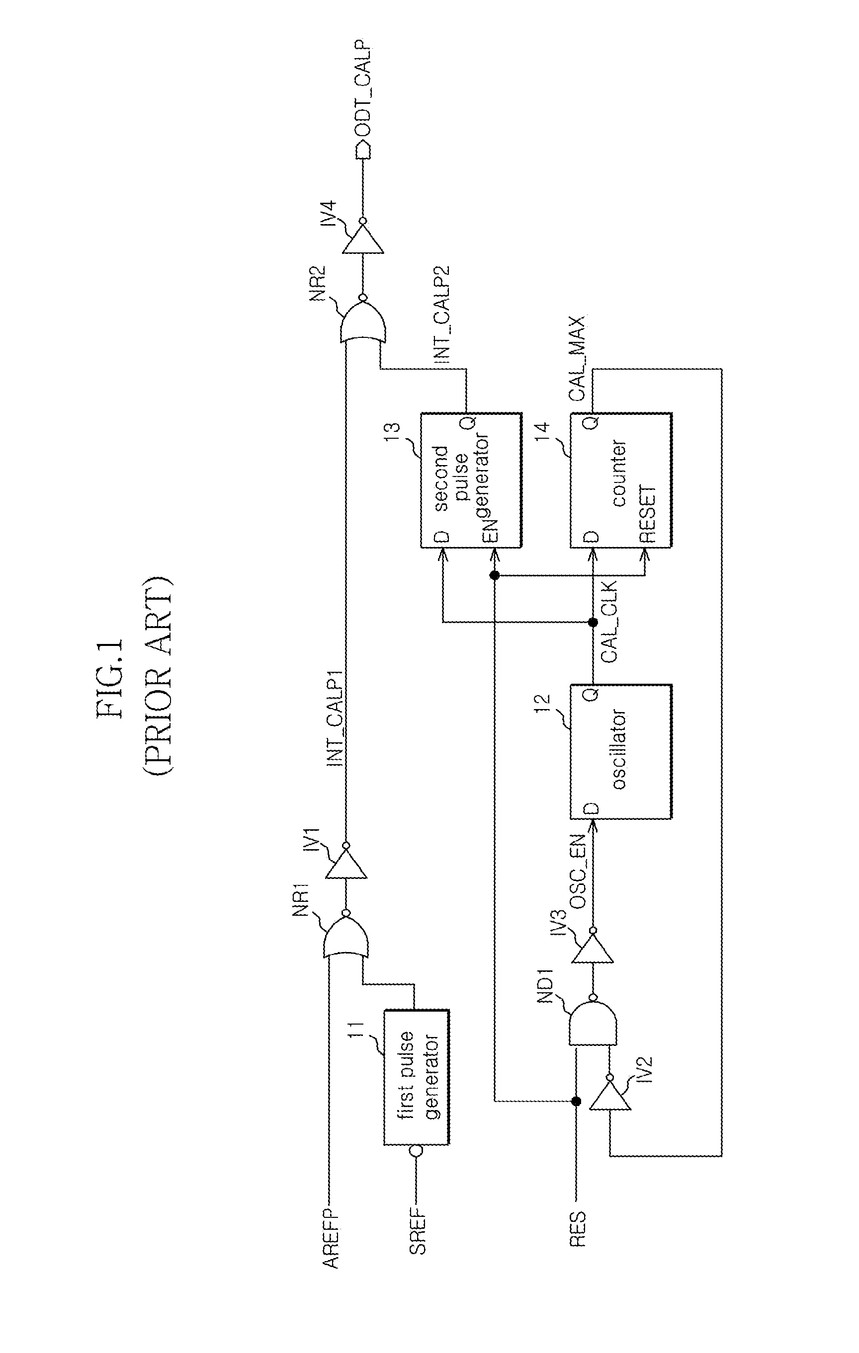
[0025]FIG. 1 is a block diagram illustrating an exemplary circuit for generating an on-die termination control signal;

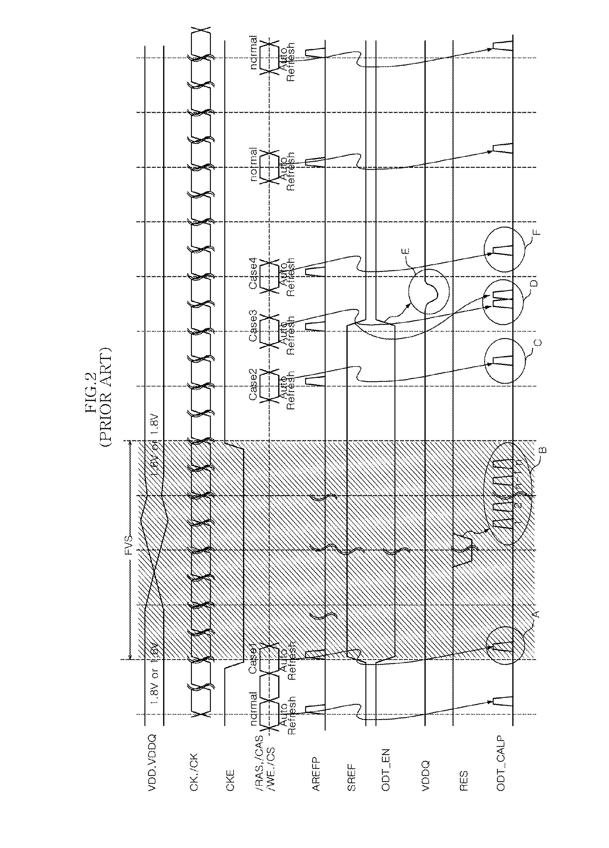
[0026]FIG. 2 is a timing diagram illustrating the operation of the circuit illustrated in FIG. 1;

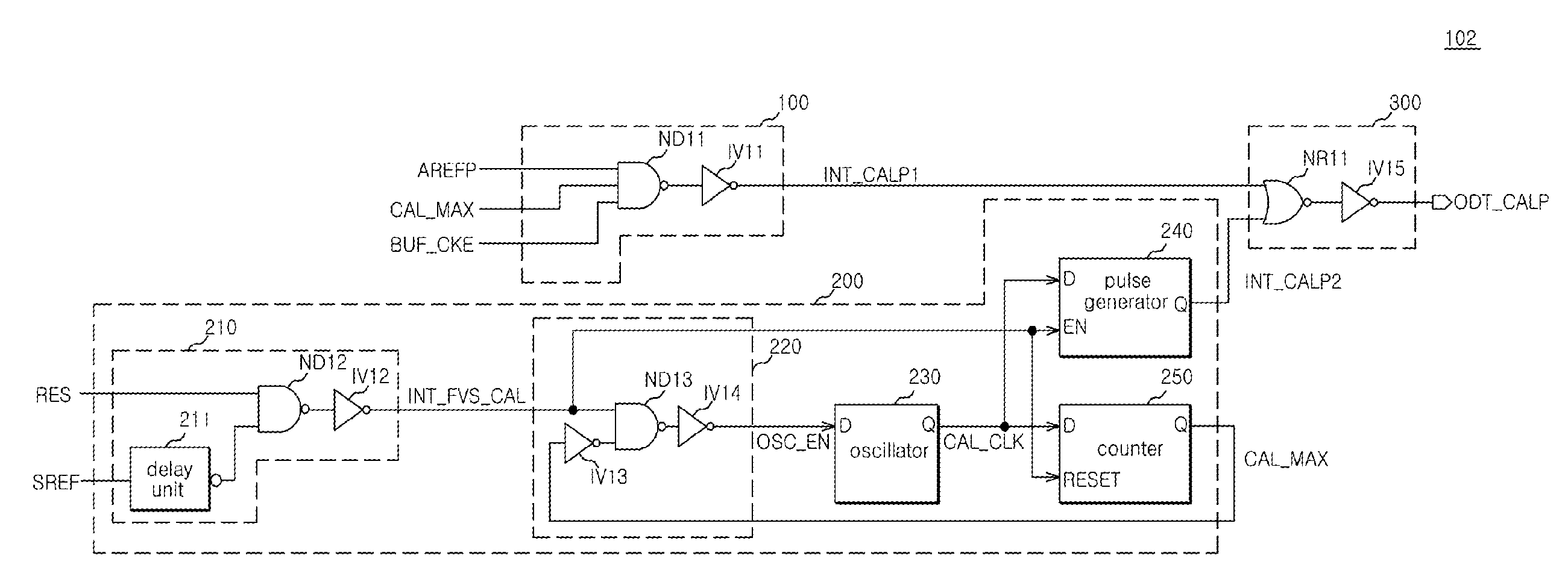
[0027]FIG. 3 is a block diagram illustrating a circuit configured to generate an on-die termination control signal according to one embodiment;

[0028]FIG. 4 is a circuit diagram illustrating a circuit configured to generate an on-die termination control signal according to another embodiment; and

[0029]FIG. 5 is a timing diagram illustrating the operation of the circuit of FIGS. 3 and 4.

DETAILED DESCRIPTION

[0030]FIG. 3 is a block diagram illustrating an example circuit 101 configured to generate an on-die termination control signal according to one embodiment. Referring to FIG. 3, the circuit 101 can include a first signal generation ...


PUM


Abstract

A circuit for generating an on-die termination control signal can include a first signal generation block configured to generate a first signal to prevent a first on-die terminal control from being performed in a frequency/voltage switching period, a second signal generation block configured to generate a second signal to perform a second on-die termination control at an initial stage of operation, and a signal output block configured to generate the on-die termination control signal by combining the first and second signals.

Description

CROSS-REFERENCES TO RELATED APPLICATION[0001]The present application claims the benefit under 35 U.S.C. 119(a) of Korean application number 10-2007-0057582, filed on Jun. 13, 2007, in the Korean Intellectual Property Office which is incorporated by reference in its entirety as if set forth in full.BACKGROUND[0002]1. Technical Field[0003]The disclosures herein relate to a semiconductor memory apparatus and, more particularly, to a circuit for generating an on-die termination control signal to operate an on-die termination circuit of a semiconductor memory apparatus.[0004]2. Related Art[0005]Conventional on-die termination control refers to an operation which allows a driver to have impedance identical to a reference impedance regardless of PVT (process, voltage and temperature) fluctuations. In order to perform the on-die termination control, an on-die termination circuit is provided in a semiconductor memory apparatus. In addition, a circuit for generating an on-die termination cont...

Claims


Application Information

Patent Timeline
IPC IPC(8): H03K17/16H03K19/003H03K3/00
CPCG11C5/063G11C7/04G11C7/1051G11C7/1057G11C11/4093G11C7/1084G11C11/406G11C11/40611G11C11/40615G11C7/1078G11C7/22H03K19/017545H04L25/0278
Inventor PARK, NAK KYU
Owner SK HYNIX INC
Why Eureka
Try Eureka