Milling machine control system

Active Publication Date: 2020-06-25
ROADTEC
View PDF5 Cites 2 Cited by
  • Summary
  • Abstract
  • Description
  • Claims
  • Application Information

AI Technical Summary

Benefits of technology

[0025]The invention comprises a milling machine having a frame to which a milling drum is mounted, and a primary drum drive assembly for driving the milling drum. The milling machine also includes a ground-engaging drive assembly for driving the milling machine along a roadway and a drive control system for the ground-engaging drive assembly. A lifting column is attached between the frame of the milling machine and the ground-engaging drive assembly. The lifting column includes a linear actuator which can raise and lower the frame of the machine with respect to the roadway. A load cell sensor mounted to the lifting column is adapted to determine if the lifting column is not supporting at least a predetermined portion of the weight of the milling machine. The load cell sensor is attached to a top bracket of the lifting column in such a manner that it does

Problems solved by technology

Without prior surface treatment, however, this method of repair generally results in the application of insufficient quantities of paving material in the rutted, pot-holed or otherwise damaged areas, because the overlay will be applied at the same rate per unit of roadway width in damaged areas (which have a greater depth to be filled across the width) as in the undamaged areas.
The resulting reduced thickness in the overlay of the previously damaged areas will lead to renewed rutting or other wear damage in the new pavement in relatively short order.
Roadway repair without milling can require the raising of road shoulders, guardrails and manhole covers and the adjustment of overpass clearances, all of which are unnecessary if a proper milling technique is employed.
However, circumstances may arise in which the milling drum encounters increased density material in the roadway during a milling operation, causing the machine to rise up out of the cut.
This will cause an undesirable portion of the weight of the milling machine to be supported by the milling drum instead of the lifting columns, and may result in a loss of steering or braking control because of insufficient contact between the drive assemblies on the lifting columns and the roadway.
This occurrence is dangerous for the machine operator and may also lead to damage of the milling machine.
Furthe

Method used


Image

  • Milling machine control system
  • Milling machine control system
  • Milling machine control system

Examples


Example

[0042]This description of the preferred embodiments of the invention is intended to be read in connection with the accompanying drawings, which are to be considered part of the entire written description of this invention. The drawing figures are not necessarily to scale, and certain features of the invention may be shown exaggerated in scale or in somewhat schematic form in the interest of clarity and conciseness.

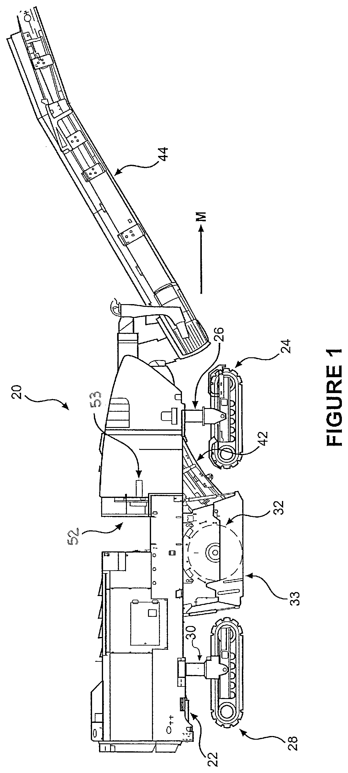
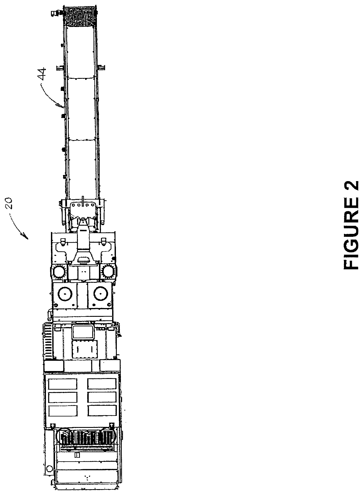
[0043]As shown in FIGS. 1 and 2, a milling machine that is equipped with a preferred embodiment of the invention is indicated generally at 20. This machine comprises a mobile vehicle having a frame 22 and a plurality of ground-engaging drive assemblies that are attached to lifting columns, including right front track drive assembly 24 which is attached to lifting column 26, a left front track drive assembly (not shown but substantially similar to right front track drive assembly 24), right rear track drive assembly 28 which is attached to right rear lifting column 30, and ...


PUM


Abstract

A milling machine includes a primary drum drive assembly for its milling drum, and a ground-engaging drive assembly for driving the milling machine along a roadway. A lifting column is attached between the frame and the ground-engaging drive assembly. The lifting column includes a linear actuator which can raise and lower the frame of the machine with respect to the roadway. A sensor mounted to the lifting column is adapted to determine if the lifting column is not supporting at least a predetermined portion of the weight of the milling machine. A controller is operatively attached to the drive assemblies and to the sensor, and is adapted to receive from the sensor a signal indicating that the lifting column is not supporting the predetermined portion of the weight of the milling machine. Upon receipt of such signal, the controller will automatically control certain machine functions.

Description

CROSS-REFERENCE TO RELATED APPLICATION[0001]This application is a continuation-in-part of U.S. patent application Ser. No. 16 / 596,271, which was filed on Oct. 8, 2019, which itself is a continuation-in-part of U.S. patent application Ser. No. 16 / 139,273 (now abandoned), which was filed on Sep. 24, 2018 and claims the benefit of U.S. Provisional Patent Application No. 62 / 582,715, which was filed on Nov. 7, 2017.FIELD OF THE INVENTION[0002]This invention relates generally to a system for automatically taking action to control a milling machine during the performance of a milling operation when the system anticipates that the machine drive assembly may lose traction and / or that the milling drum may experience a kick-back event. More particularly, the system allows for slowing or stopping a drive assembly of a milling machine during the performance of a milling operation when the system anticipates that the drive assembly may lose traction, and / or for stopping the rotation of the millin...

Claims


Application Information

Patent Timeline
IPC IPC(8): E01C23/088E01C23/12G01G19/12
CPCE01C23/088E01C23/127G01G19/12
Inventor AVANS, TODDBEVILL, JAMES H.SWEARINGEN, DAVID
Owner ROADTEC
Why Eureka
Try Eureka