Exhaust purification system

Active Publication Date: 2018-03-08
ISUZU MOTORS LTD
View PDF7 Cites 0 Cited by
  • Summary
  • Abstract
  • Description
  • Claims
  • Application Information

AI Technical Summary

Benefits of technology

[0010]According to the exhaust purification system of the disclosure, it is possible to effectively suppress deterioration in fuel consumption by reliably p

Problems solved by technology

In the device that performs, in combination, the air-based control and the injection-based control, if rich injection by the injection-based control is started before the intake air amount is re

Method used


Image

  • Exhaust purification system
  • Exhaust purification system
  • Exhaust purification system

Examples


Example

[0021]Hereinafter, an exhaust purification system in accordance with an illustrative embodiment of the present invention will be described with reference to the accompanying drawings.

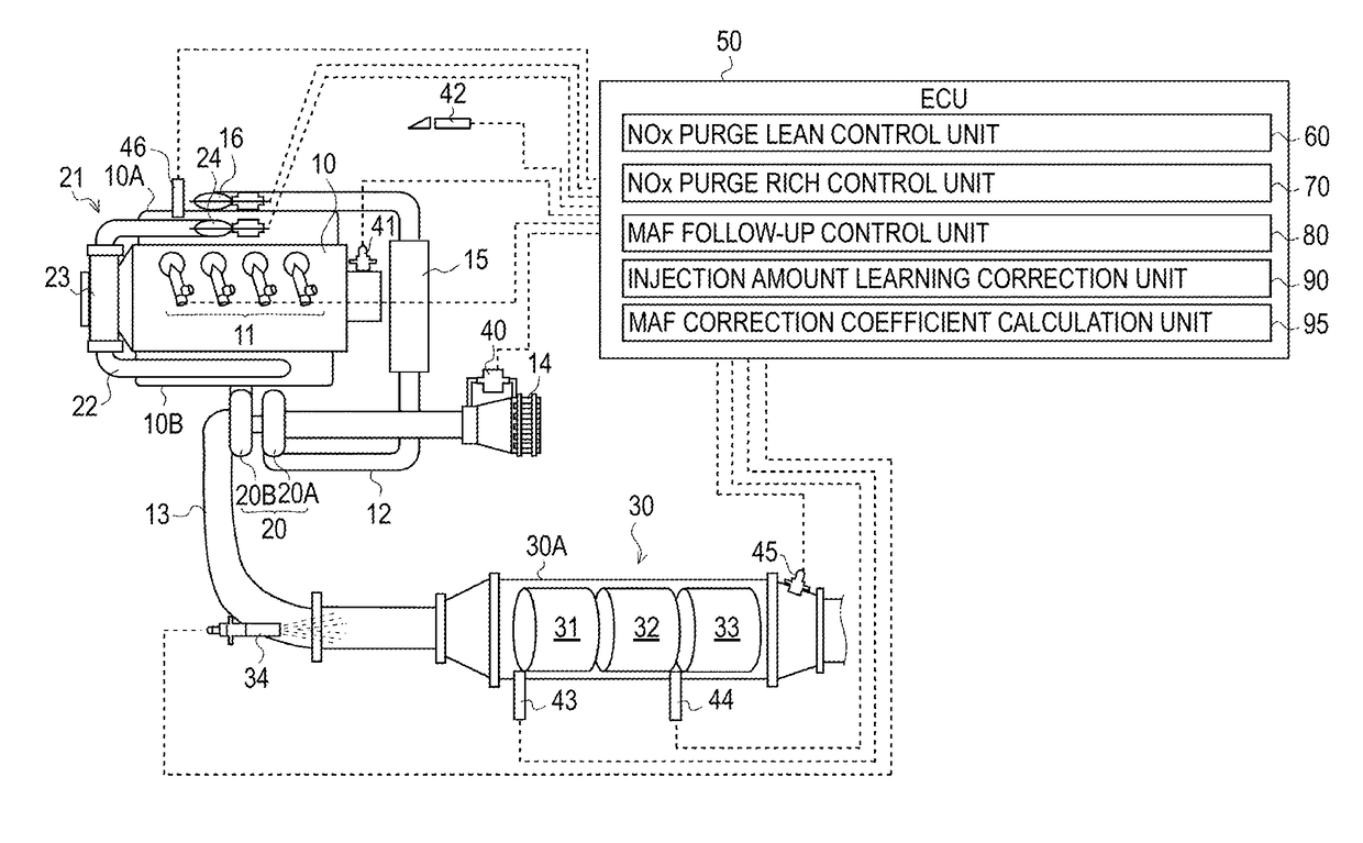
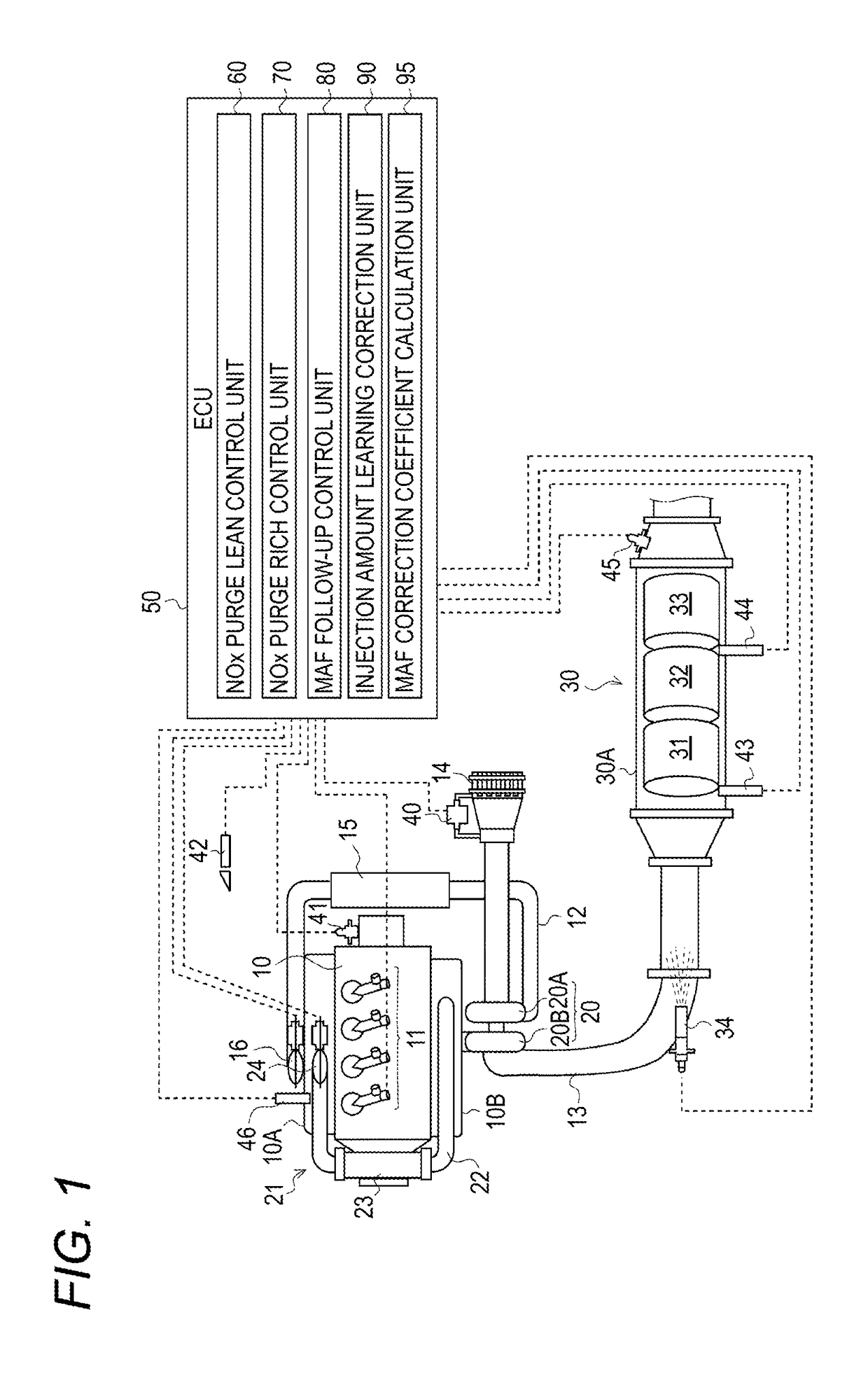
[0022]As shown in FIG. 1, each cylinder of a Diesel engine (hereinafter, simply referred to as ‘engine’) 10 is provided with an injector 11 configured to directly inject high-pressure fuel accumulated to a common rail (not shown) into each cylinder. A fuel injection amount and a fuel injection timing of each injector 11 are controlled in correspondence to instruction signals that are input from an electronic control unit (hereinafter, referred to as ‘ECU’) 50.

[0023]An intake manifold 10A of the engine 10 is connected with an intake passage 12 for introducing therein fresh air, and an exhaust manifold 10B is connected with an exhaust passage 13 for discharging exhaust to an outside. The intake passage 12 is provided with an air cleaner 14, an intake air amount sensor (hereinafter, referred to as ‘MAF sen...


PUM


Abstract

An exhaust purification system including a NOx catalyst 32 provided in an exhaust passage of an internal combustion engine 10 and purifying NOx in exhaust; a MAF sensor 40 for acquiring an air flow-rate of the internal-combustion engine 10; a control unit 60, 70 that execute catalyst regeneration treatment of recovering a NOx purification ability of the NOx catalyst 32 by performing, in combination, air-based control of reducing air flow-rate of the internal-combustion engine 10 to a predetermined target air flow-rate and injection-based control of increasing a fuel injection amount, wherein, in a case of executing the catalyst regeneration treatment, the control unit 60, 70 starts with the air-based control and starts the injection-based control when the air flow-rate acquired by the MAF sensor 40 is reduced to the target air flow-rate.

Description

TECHNICAL FIELD[0001]The present invention relates to an exhaust purification system.BACKGROUND ART[0002]In the related art, a NOx-occlusion-reduction-type catalyst is known, as a catalyst for reducing and purifying a nitrogen compound (NOx) in exhaust emitted from an internal combustion engine. When the exhaust is in a lean atmosphere, the NOx-occlusion-reduction-type catalyst occludes NOx contained in the exhaust, and when the exhaust is in a rich atmosphere, the NOx-occlusion-reduction-type catalyst detoxifies and releases the occluded NOx with hydrocarbon contained in the exhaust by reduction and purification. For this reason, when a NOx occlusion amount of the catalyst reaches a predetermined amount, it is necessary to periodically perform NOx purge of enriching the exhaust by exhaust pipe injection or post injection so as to recover a NOx occlusion capacity (for example, refer to Patent Documents 1 and 2).PRIOR ART REFERENCEPatent Document[0003]Patent Document 1: JP-A-2008-202...

Claims


Application Information

Patent Timeline
IPC IPC(8): B01D53/94B01D53/96F01N3/08F01N3/20F01N3/24F01N3/36F02D41/04
CPCB01D53/9422B01D53/96F01N3/0871F01N3/0842F01N3/20F01N3/24F01N3/36F02D41/04F02D43/00B01D53/94F01N3/08F01N3/0814F02D41/027F02D41/0275F02D41/1475F02D41/3064F02D41/307F01N2260/04F01N2430/06F02D2041/0022F02D2250/21F02D41/0235F02D41/1454F02D41/1463F02D41/182F02D41/2448F02D41/2454F02D41/405F02D2200/0802F02D2200/602
Inventor NAKADA, TERUOSAKAMOTO, TAKAYUKINAGAOKA, DAIJIYUZA, HIROYUKI
Owner ISUZU MOTORS LTD
Why Eureka
Try Eureka