Diesel engine

Inactive Publication Date: 2005-01-11
ISUZU MOTORS LTD
View PDF10 Cites 39 Cited by
  • Summary
  • Abstract
  • Description
  • Claims
  • Application Information

AI Technical Summary

Benefits of technology

f the above problems, and it is an advantage of the present invention to realize favorable combustion without any aggravation of the exhaust gas or fuel consumption by preventing problems such as adhesion of the fuel jet mist to the inside walls of the cylinder and the like in cases where pre-mixed combustion based on an early-stage injection and a main injection is realized.
The present invention provides a diesel engine comprising a fuel injector which injects fuel into a cylinder, and fuel injection control means for controlling the amount of fuel that is injected from this fuel injector and the liming of this fuel injection, wherein the abovementioned fuel injection control means performs an early-stage injection of a relatively small amount of fuel divided into a plurality of injections in the compression stroke, and performs a main injection of a relatively large amount of fuel after a specified period has elapsed following the completion of the early-stage injection, the abovementioned early-stage injection is performed using a fuel injection amount and fuel injection timing which are such that the generation of heat caused by fuel of the early-stage injection occurs in the vicinity of compression top dead center, and the abovementioned main injection is performed using a fuel injection amount and fuel injection timing which are such that the generation of heat caused by fuel of the main injection occurs after the generation of heat caused by fuel of the early-stage injection has been completed.
Preferably, the abovementioned fuel injection control means perform the initial injection of the abovementioned early-stage injection at a timing after 80° BTDC and before 40° BTDC.
Preferably, furthermore, the abovementioned fuel injection control means performs the abovementioned main injection after compression top dead center.
Furthermore, the present invention provides a fuel injection method for a diesel engine, wherein the early-stage injection of a relative

Problems solved by technology

However, in this pilot and main injection, since the main-injection fuel suddenly enters the combustion chamber in which combustion caused by the pilot injection, the drawback of smoke generation is encountered.
Furthermore, the drawback of the generation of NOx by the combustion of the pilot-injection fuel is also encountered.
However, in this combustion method, since fuel injection is performed in a state in which the interior of the cylinder is at a low pressure and the air density is low, i.e., during the transition from the intake stroke to the compression stroke, the penetration of the fuel jet mist is relatively strong, so that the fuel jet mist directly collides with and adheres to the inside walls of the cylinder.
As a result, problems such as the exhaust of unburned fuel (HC), an aggravation of CO accompanying incomplete combustion and the like arise.
Furthermore, in cases where it is attempted to create a completely uniform pre-mixture inside the cylinder, it is desirable to perform fuel injection at as early a stage as possible, e.g., during the intake stroke; if this is done, however, it becomes difficult to cause auto-ignition of the pre-mixture at the desired timing, so that the combustion period tends to become unstable.
Even in this case, however, various problems such as the problem of adhesion of the fuel injected by th

Method used


Image

  • Diesel engine
  • Diesel engine
  • Diesel engine

Examples


Example

A preferred embodiment of the present invention will be described below with reference to the attached figures.

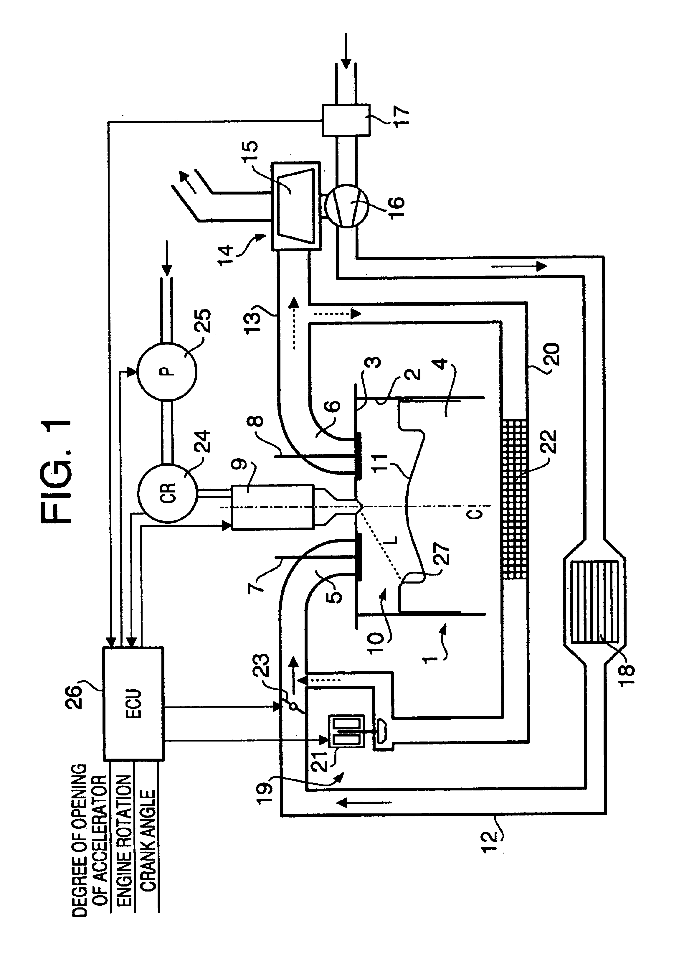
FIG. 1 shows a diesel engine constituting the present embodiment. This engine is a direct-injection diesel engine for use in vehicles, and comprises a common rail fuel injection control device as fuel injection control means. For convenience, only a single cylinder is shown in the figures; however, this engine may also naturally be a multi-cylinder engine.

1 indicates the engine main body; this is constructed from a cylinder 2, cylinder head 3, piston 4, intake port 5, exhaust port 6, intake valve 7, exhaust vale 8, injector 9 (used as a fuel injector) and the like. A combustion chamber 10 is formed inside the cylinder 2, and fuel is directly injected into the combustion chamber 10 from the injector 9. A cavity 11 is formed in the top part of the piston 4, and this cavity 11 forms a part of the combustion chamber 10. The cavity 11 forms the configuration of a re-entrant type...


PUM


Abstract

In the diesel engine of the present invention, an early-stage injection (A) is performed so that this injection is divided into a plurality of injections during the compression stroke of the engine, and a main injection (B) is performed following the completion of this early-stage injection. Furthermore, the early-stage injection is performed using an amount of fuel and timing which are such that the generation of heat caused by fuel of the early-stage injection occurs in the vicinity of compression top dead center, and the main injection is performed using an amount of fuel and timing which are such that the generation of heat caused by fuel of the main injection occurs after the generation of heat caused by fuel of the early-stage injection has been completed. Since the early-stage injection is divided into a plurality of injections, the adhesion of fuel to the inside walls of the cylinder is prevented, and pre-mixing of the fuel is promoted. Since the generation of heat caused by fuel of the main injection occurs after the generation of heat caused by fuel of the early-stage injection has been completed, there is no sudden entry of fuel injected by the main injection into the hot flame inside the cylinder; accordingly, the aggravation of smoke is prevented.

Description

BACKGROUND OF THE INVENTION1. Field of the InventionThe present invention relates to a diesel engine, and more particularly to a diesel engine in which an early-stage injection that is performed at an earlier stage than normal pilot injection, and a main injection that is performed thereafter.2. Description of the Related ArtConventionally, in diesel engines, it is known that a pilot injection and a main injection are performed. In such engines, a relatively small amount of pilot injection is first performed at a timing in the vicinity of compression top dead center (generally, around 10° BTDC to 10° ATDC), and a relatively large amount of main injection is performed immediately after this pilot injection. The fuel provided by the pilot injection is ignited immediately following injection; this acts as a flame seed that aids the ignition of the main injection. Since the ignition lag of the fuel injected in the main injections is suppressed, and rapid early-stage combustion and an ab...

Claims


Application Information

Patent Timeline
IPC IPC(8): F02D41/40F02D41/38
CPCF02D41/403F02D41/402Y02T10/44Y02T10/40
Inventor TAKAHASHI, SUSUMU
Owner ISUZU MOTORS LTD
Why Eureka
Try Eureka