Fuel cell system

Inactive Publication Date: 2007-02-08
HONDA MOTOR CO LTD
View PDF3 Cites 14 Cited by
  • Summary
  • Abstract
  • Description
  • Claims
  • Application Information

AI Technical Summary

Benefits of technology

[0015] The present invention has been made in light of the above problems, and accordingly it is an object thereof to solve the problem of flooding by giving fuel gas a channel flow speed the necessary for eliminating flooding in fuel cells while re-circulating unreacted fuel gas which has been discharged to outside the circulation channel in order to provide this channel flow speed, thereby improving the efficiency of the fuel cell system.

Problems solved by technology

However, in some cases, the gas flow speed drops due to a low load or the like.
Such a case can lead to an undesired phenomenon in which the water therewithin is not completely discharged and closes off the channel (hereafter referred to as “flooding”).
There has been a problem in that electricity generation becomes unstable when the channel of the fuel gas is closed off due to this flooding.
However, with such a method, vapor is also included in the re-circulated gas, so there has been a problem in that flooding occurs even more easily.
However, with the invention disclosed in Japanese (Unexamined) Patent Application Publication No. 2002-237322, fuel consumption efficiency decreases due to discharging the fuel gas externally in order to increase the flow speed within the fuel cell channel, thereby deteriorating the efficiency of the overall system.
Also, while the invention disclosed in Japanese (Unexamined) Patent Application Publication No. 2002-280027 is capable of reducing the external discharge amount of fuel gas, a compressor such as an electric pump or the like which is capable of blowing out water droplets in the channel of the fuel cell, becomes necessary, which leads to the problem of increased weight and size.
Further, energy necessary for driving this compressor must be supplied, meaning that the overall efficiency of the system is deteriorated to that extent.
Also, with the inventions disclosed in Japanese (Unexamined) Patent Application Publication Nos. 62-272468 and 5-13094, the hydrogen discharged from the fuel cell can be efficiently used up, but the flow speed within the reactant gas channel cannot be increased, leading to the problem that flooding easily occurs.

Method used


Image

  • Fuel cell system
  • Fuel cell system
  • Fuel cell system

Examples


first embodiment

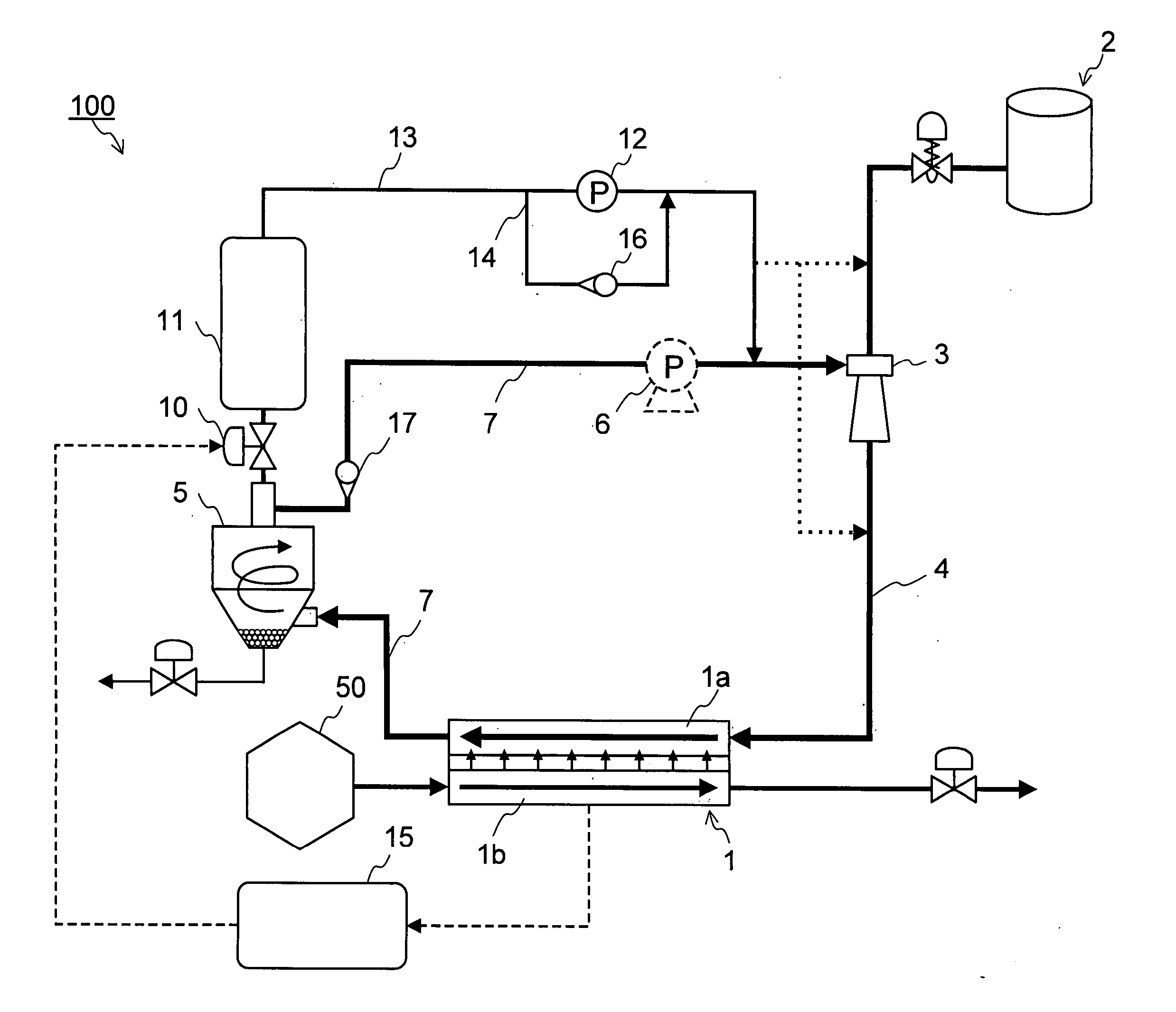
[0039] As shown in FIG. 1. the fuel cell system 100 according to the first embodiment of the present invention includes: a fuel cell 1; a supply channel 4 in which are disposed a fuel supply device 2 and an ejector pump 3; a circulation channel 7 in which are disposed a gas-liquid separator 5 and a circulation pump 6; an exhaust gas recovery channel 13 in which are disposed a first control valve 10, a first exhaust gas storage container 11, and a exhaust gas recovery pump 12; a bypass channel 14 which circumvents the exhaust gas recovery pump 12 of the exhaust gas recovery channel 13; and a control device (ECU) 15. Also, the circulation channel 7 and bypass channel 14 have check valves 16 and 17 provided. Note that the circulation pump 6 is not indispensable in the event that the ejector pump 3 is used.

[0040] The fuel cell 1 has a configuration in which a polymer electrolyte membrane formed of a cation-exchange membrane or the like is held between an anode electrode (fuel electrode...

second embodiment

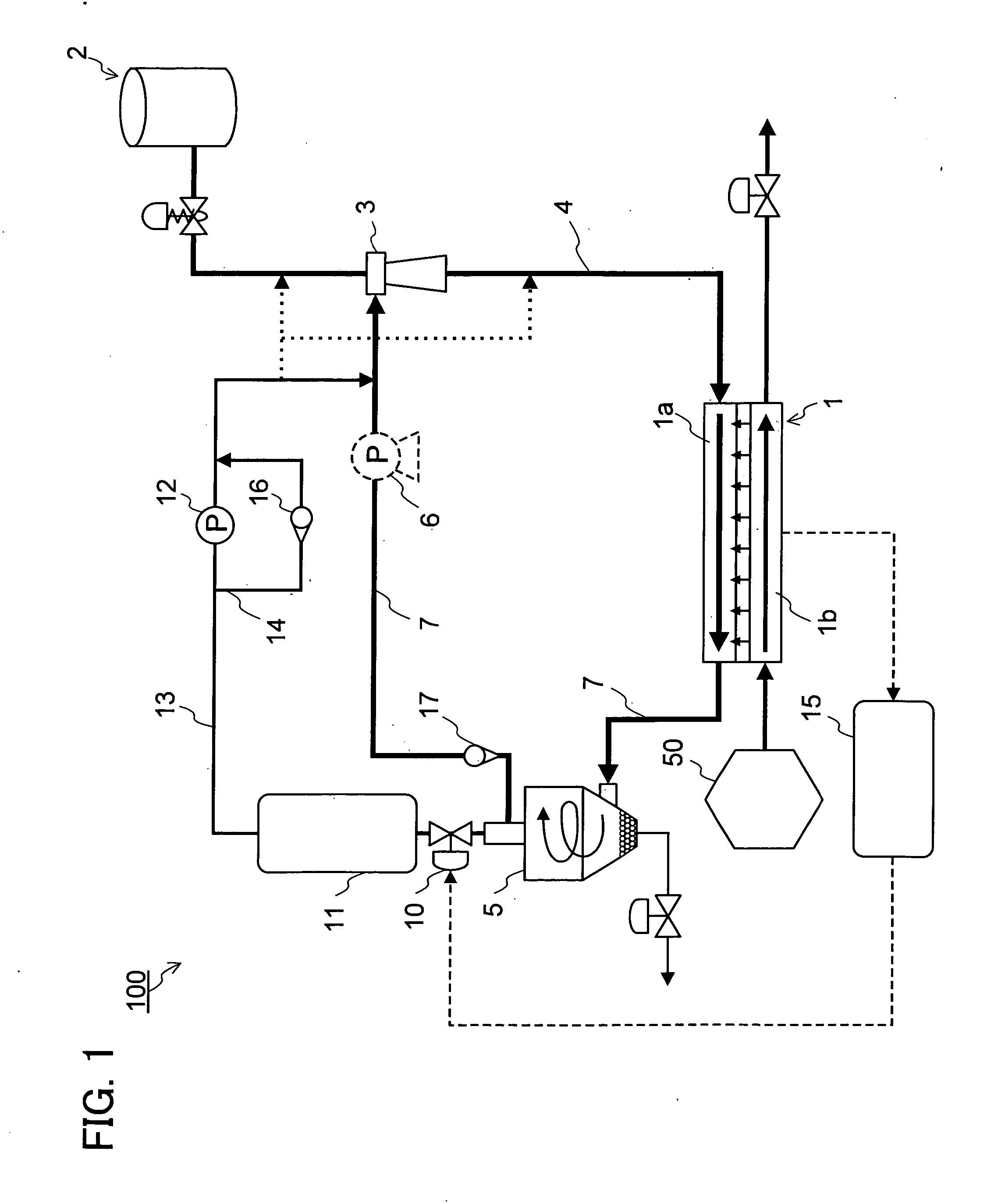
[0053] The first embodiment described an arrangement in which the exhaust gas recovery channel 13 includes the first exhaust gas storage container 11 in a negative pressure state. According to a second embodiment, a second exhaust gas storage container 11b is provided to the exhaust gas recovery channel 13, in addition to the first exhaust gas storage container 11, as shown in FIG. 2. That is to say, with the second embodiment, the exhaust gas recovery channel 13 has the first control valve 10, the first exhaust gas storage container 11, the exhaust gas recovery pump 12, the second exhaust gas storage container 11b, and a second control valve 10b, which are disposed thereat in that order along the direction of gas flow. Also, one side of the exhaust gas recovery channel 13 is connected to the gas-liquid separator 5, while the other side of the exhaust gas recovery channel 13 is connected to the supply channel 4 which in turn is connected to the anode channel 1a of the fuel cell 1.

[...

third embodiment

[0057] The first embodiment described an arrangement in which the exhaust gas recovery pump 12 is provided to the exhaust gas recovery channel 13. According to a third embodiment, an electrochemical hydrogen pump 20 may be disposed at the exhaust gas recovery channel 13, as shown in FIG. 3. The electrochemical hydrogen pump 20 is a pump having an electrolytic membrane therewithin, having functions to separate gas using a property in which only hydrogen molecules pass through the electrolytic membrane (see FIG. 5). That is to say, with the third embodiment, the exhaust gas recovery channel 13 has the first control valve 10, the first exhaust gas storage container 11, the electrochemical hydrogen pump 20, and a check valve 21 disposed thereat, in that order along the direction of gas flow. Also, one side of the exhaust gas recovery channel 13 is connected to the gas-liquid separator 5, while the other end may be connected to either the circulation channel 7 or the supply channel 4. No...


PUM


Abstract

A fuel cell system in which fuel cell flooding is eliminated by providing necessary flow speed of fuel gas within a channel while improving system efficiency of the fuel cell by re-circulating unreacted fuel gas, which has been discharged externally from a circulation channel in order to provide the flow speed within the channel. An exhaust gas storage unit which stores exhaust gas is disposed in an exhaust gas recovery channel, to store exhaust gas discharged from the anode channel of the fuel cell. Fuel consumption can be improved by re-supplying the exhaust gas to the fuel cell again. Furthermore, an exhaust storage unit is maintained at a negative pressure. This allows the flow speed of reactant gas flowing through the channel for fuel gas to be increased at the time of opening the control valve connected to the exhaust gas storage unit. Such an arrangement allows water droplets or the like remaining within the anode electrode of the fuel cell to be removed, thereby suppressing flooding. This improves the system efficiency while suppressing fuel consumption.

Description

[0001] This application is based on and claims the benefit of priority from Japanese Patent Application No. 2005-226964, filed on 4 Aug. 2005, the content of which is incorporated herein by reference. BACKGROUND OF THE INVENTION [0002] 1. Field of the Invention [0003] The present invention relates to a fuel cell system for generating electricity using fuel gas including hydrogen, and particularly relates to supplying of fuel gas in a fuel cell system. [0004] 2. Related Art [0005] In recent years, there has been great expectation for fuel cells, as means for suppressing global warming and environmental destruction, and also as next-generation electrical-generating systems, and research is being actively pursued. Fuel cells generate energy by electrochemical reaction between hydrogen and oxygen, examples thereof including phosphoric-acid fuel cells, molten carbonate fuel cells, solid-oxide fuel cells, polymer electrolyte fuel cells, and so forth. Of these, polymer electrolyte fuel cel...

Claims


Application Information

Patent Timeline
IPC IPC(8): H01M8/04H01M8/02
CPCH01M8/04097H01M8/04104Y02E60/50H01M8/04179H01M8/04164
Inventor USHIO, TAKESHIITAI, YUKIHIKOOKANO, RYU
Owner HONDA MOTOR CO LTD
Why Eureka
Try Eureka