Reception control method and receiving apparatus

Inactive Publication Date: 2008-04-03
NEC ELECTRONICS CORP
View PDF5 Cites 3 Cited by
  • Summary
  • Abstract
  • Description
  • Claims
  • Application Information

AI Technical Summary

Benefits of technology

[0009]The technology of this invention is capable of ensuring transfer efficiency and red

Problems solved by technology

Namely, in case that the timing of the restart procedure for receive the frames is too late after suspending of receipt, the transmit efficiency get worse.
On the other hand, said timing is too early, the

Method used


Image

  • Reception control method and receiving apparatus
  • Reception control method and receiving apparatus
  • Reception control method and receiving apparatus

Examples


Embodiment Construction

[0016]The embodiments of this invention are described below with reference to the drawings.

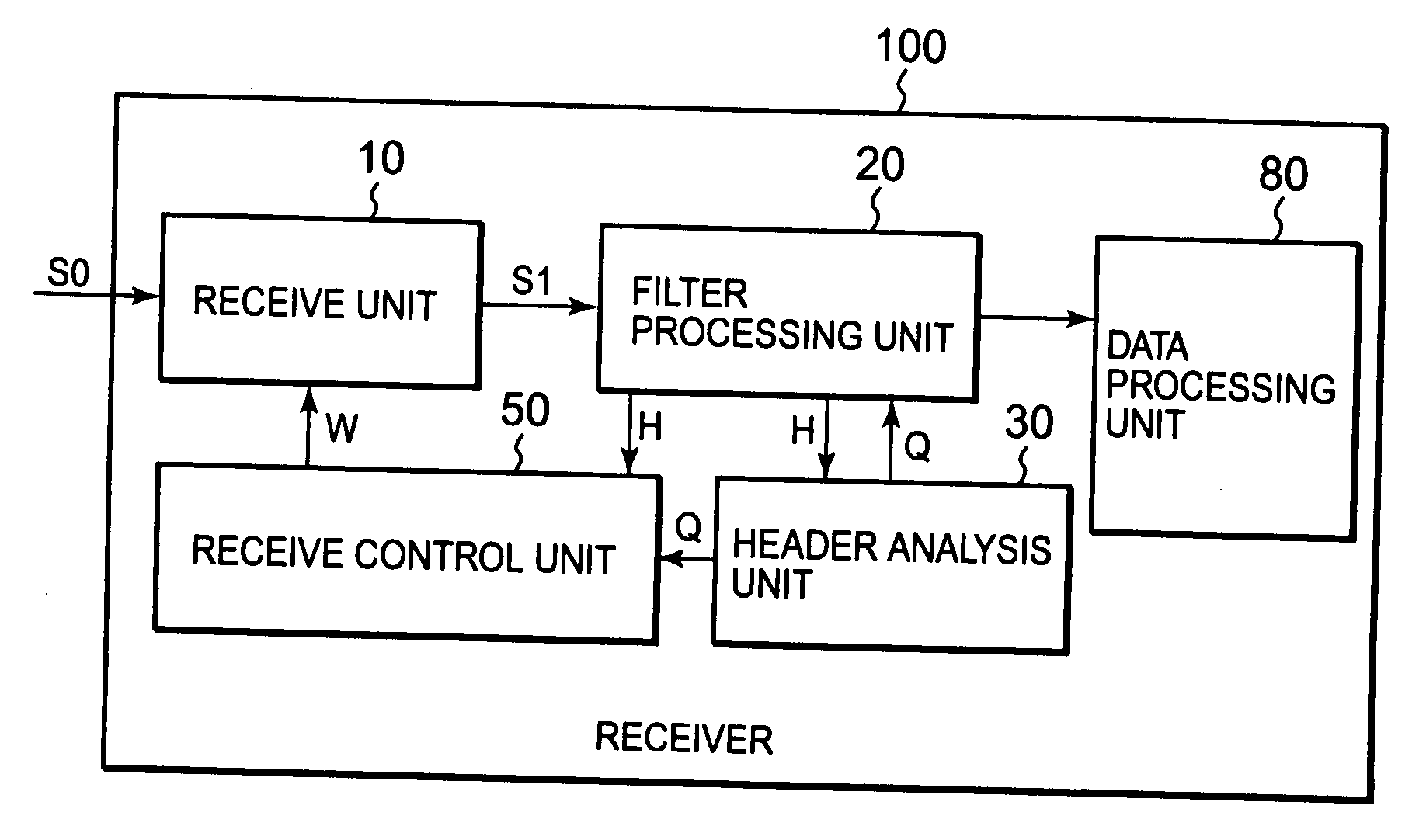
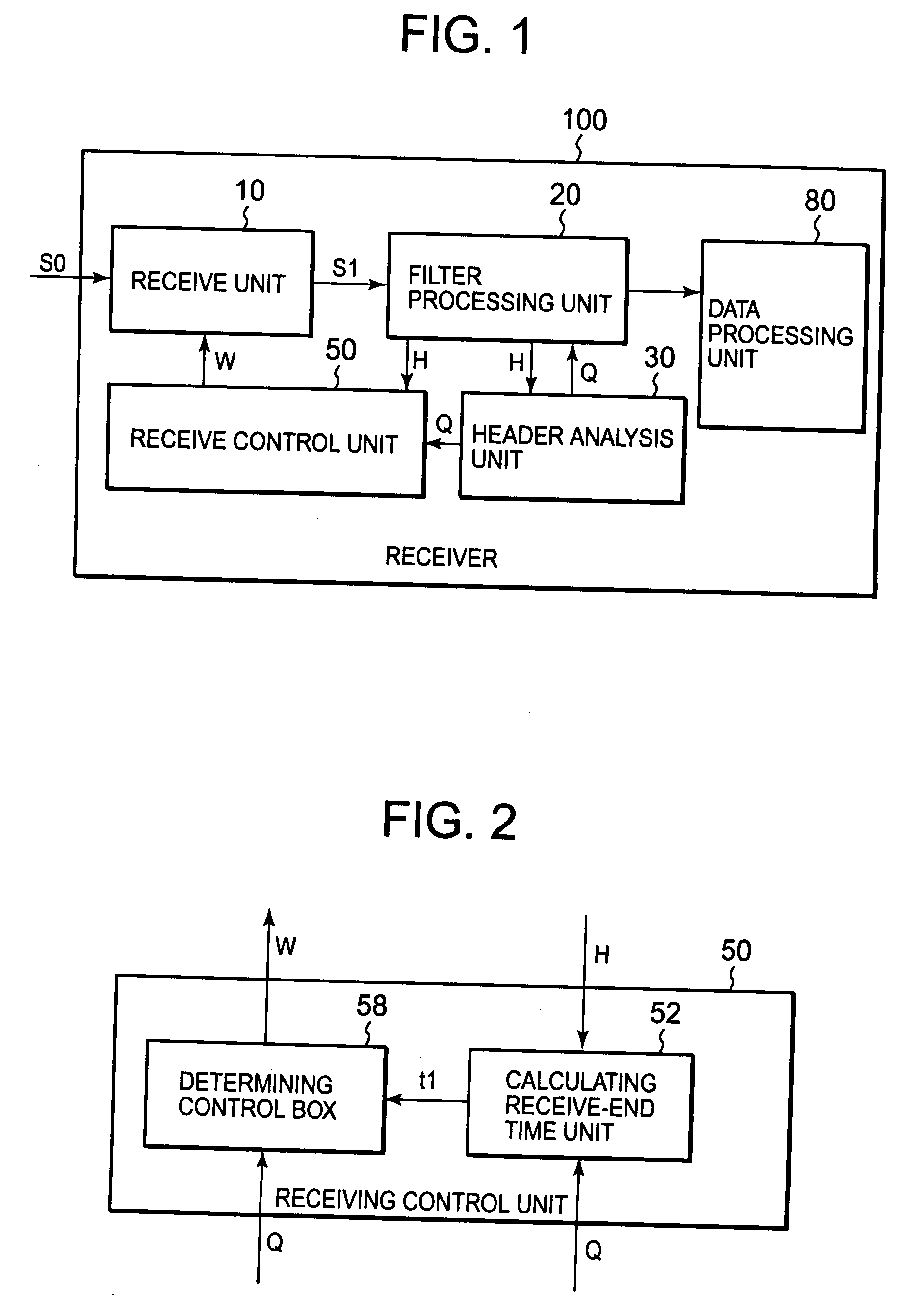
[0017]FIG. 1 is a block diagram showing the structure of a receiver 100 of the embodiment of this invention. The receiver 100 includes a receive unit 10 located on the physical layer, a filter processing unit 20, a header analysis unit 30, a receive control unit 50, and a data processing unit 80.

[0018]After receiving the signal S0 sent from the transmitter, the receive unit 10 performs processing such as synchronizing, and outputs a received signal S1 to the filter processing unit 20. The signal S0 is the communication stream contains multiple frames, and each of these frames includes a preamble, a header, and a payload which is the data body. The receive unit 10 utilizes the preamble of the frame which is included in the signal S0 to perform processing such as synchronizing, and each frame of the received signal S1 obtained in this way, includes a header and a payload. In the following descri...


PUM


Abstract

A receiving control method and receiving apparatus to ensure high transfer efficiency and reliably reduce electrical power consumption in the receiving apparatus. A receive unit receives the header and the payload of the frames in the communication stream in sequence. A header analyzer unit analyzes whether or not the applicable frame is an unwanted frame from the frame accept-reject information included in the frame header during receiving. Calculating receive-end time unit in the receive control unit calculates the receive-end time t1 of the unwanted frame. Determining control unit stops the operation of the receive unit during the stop period based on the receive-end time t1 of the unwanted frame.

Description

BACKGROUND OF THE INVENTION[0001]1. Field of the Invention[0002]This invention relates to technology for receiving frames in communications.[0003]2. Description of Related Art[0004]Efforts to reduce electrical power consumption in devices are being made in various fields. For example, in the field of broadcasting, the technology disclosed in JP-A No. 2001-69106 discloses the technology for reducing electrical power consumption in a set box that receives broadcast waves transmitted by satellite broadcast, terrestrial broadcast, cable, and so on. Next the multiple elementary streams which included in the communication stream multiplexed onto the broadcast wave are multiply-separated, and further demodulates and outputs these streams as video or audio signals. This technology utilizes the fact that the actual data (also known as “payload”) in the transport packet need not be processed unless the identifier included in the header of the transport packet in the received communication str...

Claims


Application Information

Patent Timeline
IPC IPC(8): H04L12/26
CPCH04L69/22H04L49/90
Inventor HARUTA, YOSHIHIRO
Owner NEC ELECTRONICS CORP
Why Eureka
Try Eureka