Print Buffer Unit

Inactive Publication Date: 2007-09-20
SEIKO EPSON CORP
View PDF9 Cites 0 Cited by
  • Summary
  • Abstract
  • Description
  • Claims
  • Application Information

AI Technical Summary

Benefits of technology

[0011] According to the print buffer unit of the present invention, the print-image displaying section is preferably capable of maintaining displayed content even after power supply is cut.
[0012] According to the above-d

Problems solved by technology

However, the known print buffer units cannot display content

Method used


Image

  • Print Buffer Unit
  • Print Buffer Unit
  • Print Buffer Unit

Examples


Example

[0025] A print buffer unit according to an embodiment of the present invention will now be described with reference to the drawings.

Embodiment

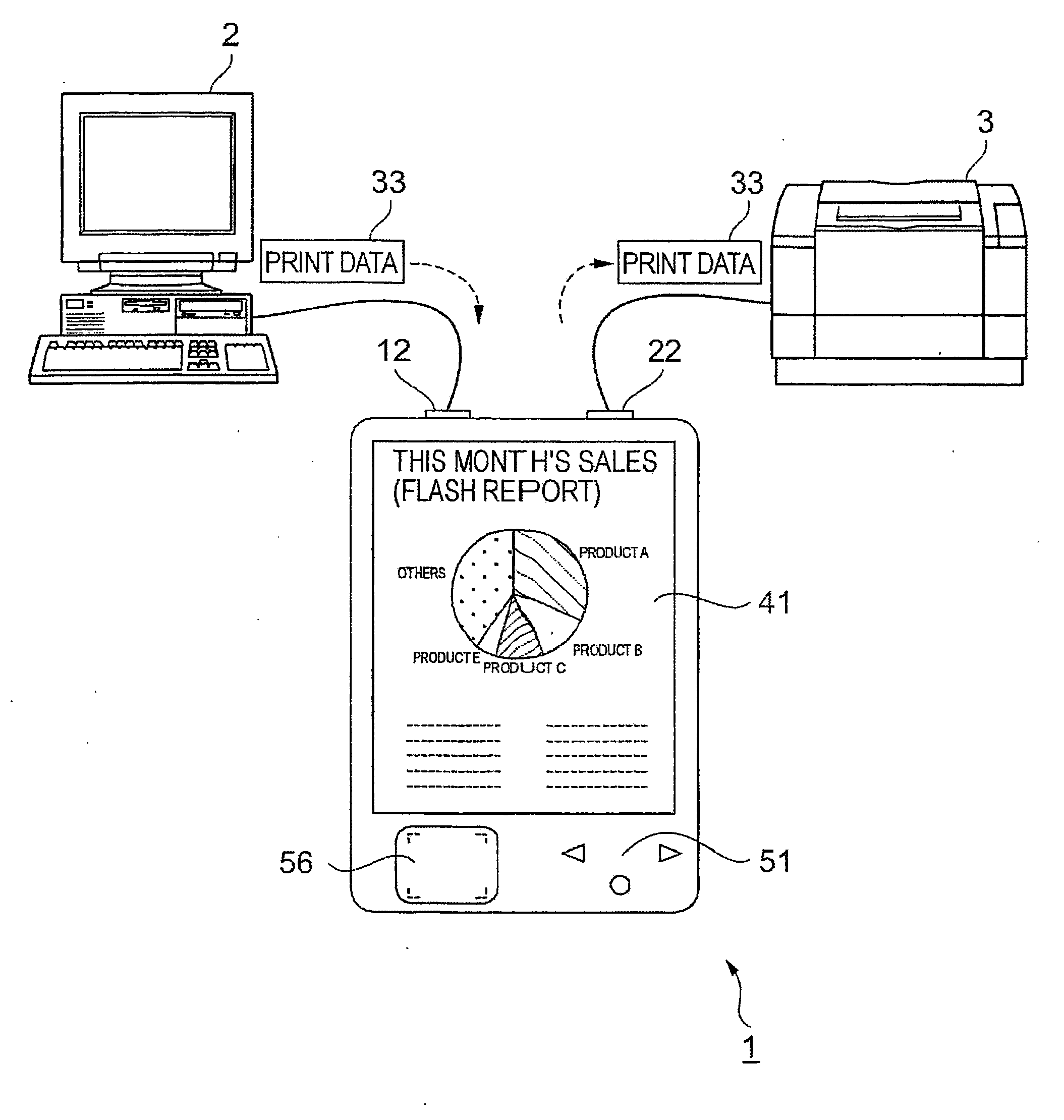
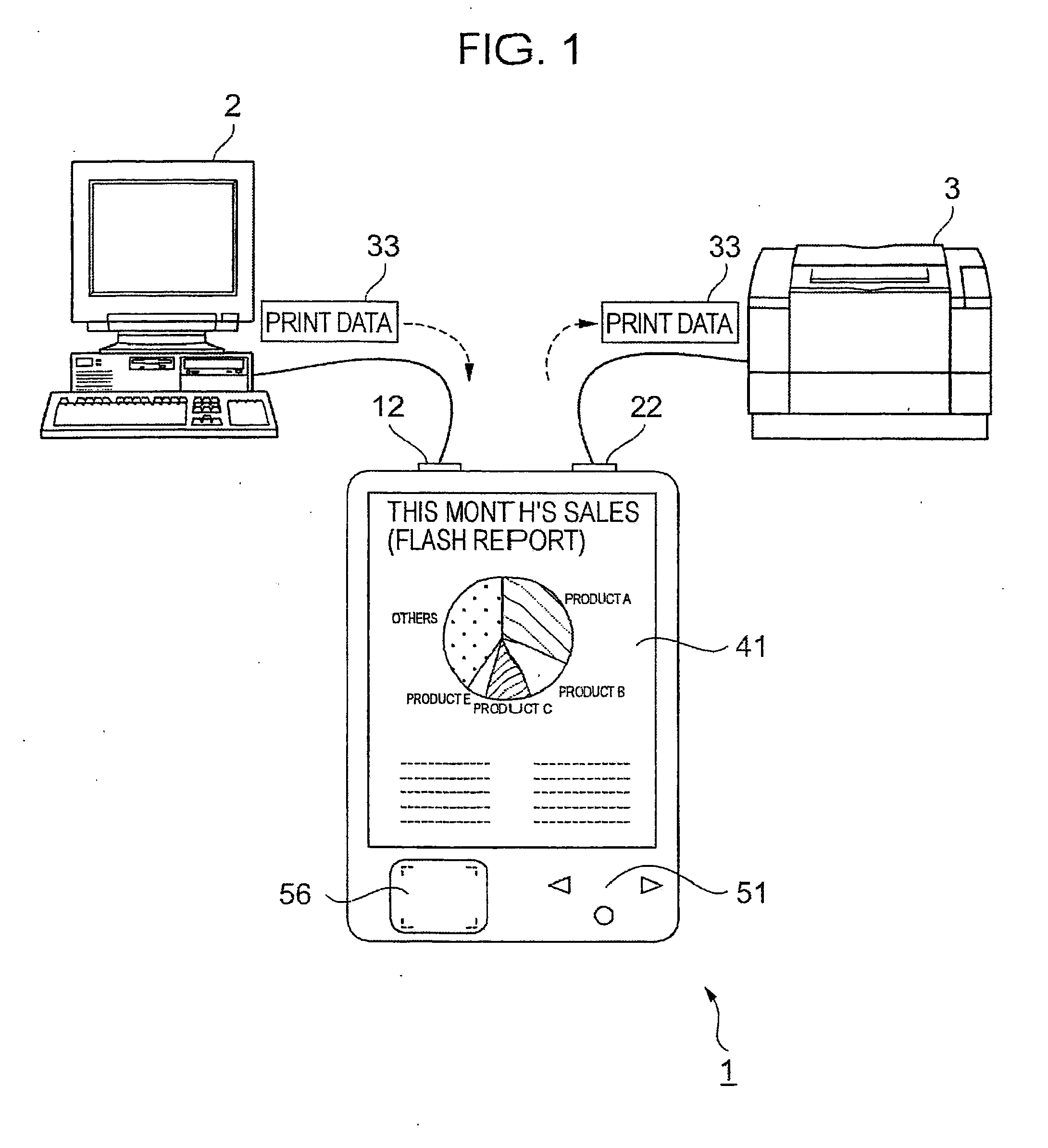
[0026]FIG. 1 is a schematic view illustrating an outline configuration of a print buffer unit 1 according to an embodiment of the present invention. As shown in FIG. 1, the print buffer unit 1 is connected to a host apparatus 2 and a printer 3. Print data 33 created by the host apparatus 2 is sent to the print buffer unit 1, processed in the print buffer unit 1, and then sent to the printer 3 to be printed.

[0027] The print buffer unit 1 includes a display panel 41, an operation switch 51, and a modification pad 56 on the top surface thereof. The print buffer unit 1 further includes a data-inputting port 12 and a data-outputting port 22 on a side surface thereof. The display panel 41 displays a print image to be printed on the printer 3. The operation switch 51 is an input device for a user that operates the print buffer unit 1. The modifica...


PUM


Abstract

A print buffer unit temporally storing print data to be printed on a printer includes a data-storing section storing the print data, a print-image creating section creating a print image from the print data, and a print-image displaying section displaying the print image.

Description

TECHNICAL FIELD [0001] The present invention relates to print buffer units temporally storing print data that are created by host apparatuses such as computers and that are to be printed on printers. BACKGROUND ART [0002] Known print buffer units temporally storing print data to be printed on printers usually include input-output sections, storage sections, and controlling sections, and are of a desktop type driven with power for households. A print buffer unit described in Japanese Unexamined Utility Model Registration Application Publication No. 6-43745 can be moved while temporally storing print data therein by employing a portable power source. [0003] However, the known print buffer units cannot display content of the print data temporally stored in the print buffer units. Therefore, when multiple pieces of print data are temporally stored in the print buffer units, or when the print buffer units are moved while temporally storing print data therein, users of the print buffer un...

Claims


Application Information

Patent Timeline
IPC IPC(8): G09G5/36B41J5/30B41J21/00G06F3/12
CPCG06F3/1207G06F3/1285G06F3/1259G06F3/1256
Inventor TANAKA, DAIKOYAMA, FUMIOKODAMA, YOSHIYUKI
Owner SEIKO EPSON CORP
Why Eureka
Try Eureka