Arrangement for releasably holding a component in a fixed position on a shaft

a technology for releasably holding components and fixing positions, which is applied in the direction of screws, nuts, bolts, etc., can solve the problems of high vibration and unsuitable applications, and achieve the effect of improving and being relatively simpl

Active Publication Date: 2010-04-27
PRATT & WHITNEY CANADA CORP
View PDF20 Cites 11 Cited by
  • Summary
  • Abstract
  • Description
  • Claims
  • Application Information

AI Technical Summary

Benefits of technology

[0003]It is therefore an object to provide an improved and relatively simple way of holding a component in a fixed position on a shaft.
[0005]In a second aspect, the present concept provides a holding arrangement for a component to be mounted on a shaft, the arrangement comprising: a lockplate; means for preventing rotation of the lockplate with reference to the shaft; a nut to be mounted adjacent to the lockplate; means for securing the nut in a threaded engagement on the shaft; a lockwasher to be mounted around the nut; means for preventing rotation of the lockwasher with reference to the shaft; a resilient ring to be mounted between the nut and the lockwasher; and means for preventing the lockwasher from moving away from the lockplate.

Problems solved by technology

While these arrangements are suitable for many applications, it is not necessarily suitable for applications involving, for instance, high rotational speeds, sudden accelerations and / or decelerations, and / or high levels of vibrations.

Method used


Image

  • Arrangement for releasably holding a component in a fixed position on a shaft
  • Arrangement for releasably holding a component in a fixed position on a shaft
  • Arrangement for releasably holding a component in a fixed position on a shaft

Examples


Embodiment Construction

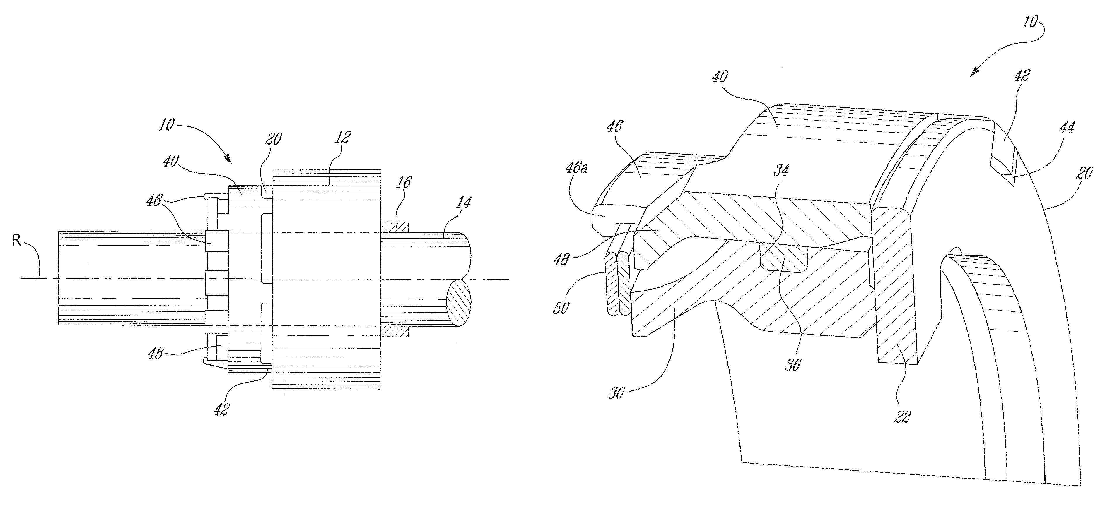
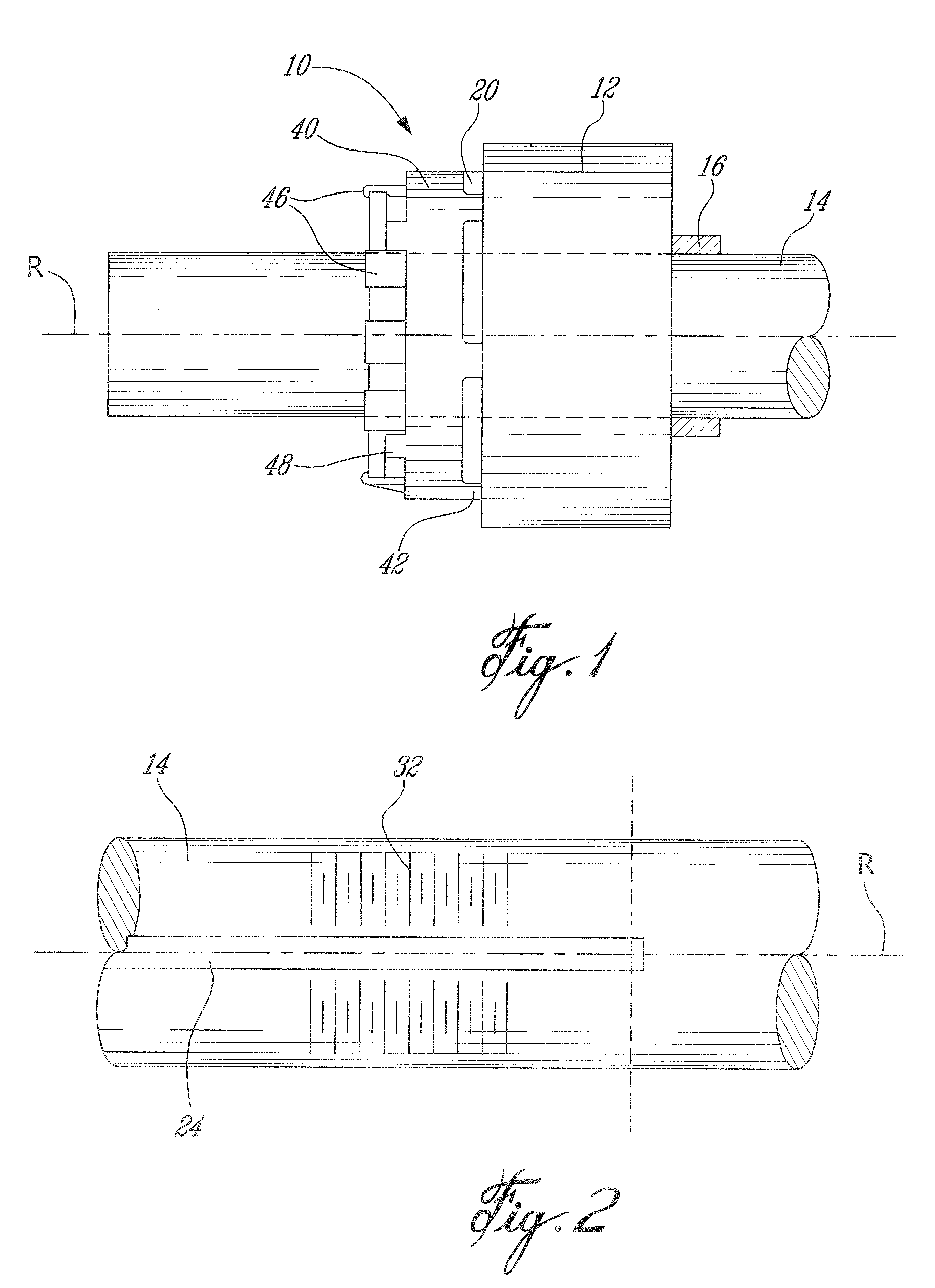
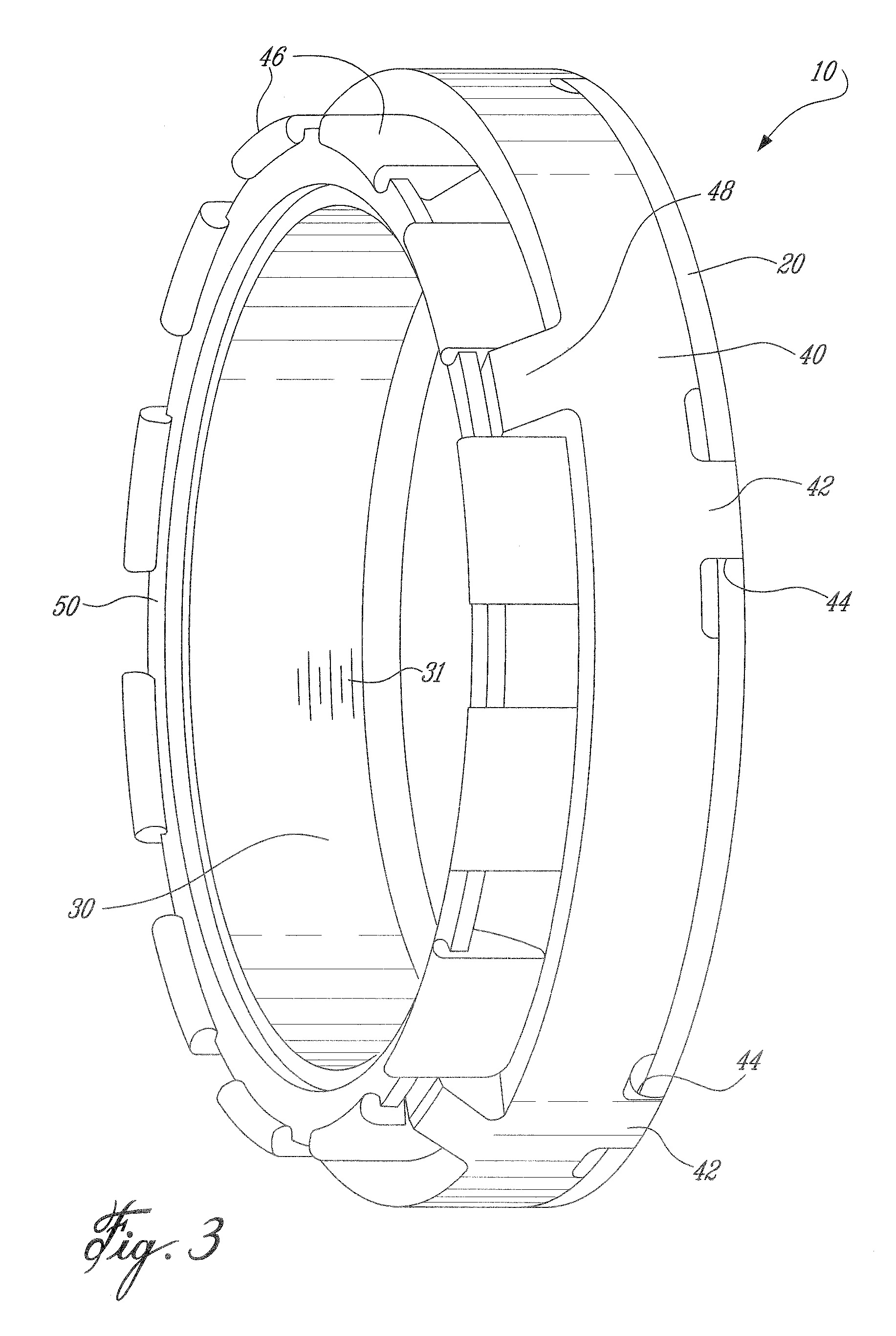
[0013]FIG. 1 schematically shows an example of an arrangement 10 for releasably holding a component 12 in a fixed position on a shaft 14. The arrangement 10 comprises a plurality of parts that are coaxially mounted around the shaft 14. The shaft 14 rotates around a rotation axis R. The illustrated arrangement 10 being designed for high rotation speed applications, the various parts are symmetrically disposed around the rotation axis R and balanced so as to minimize vibrations during the rotations.

[0014]A non-limitative list of components 12 with which the arrangement 10 can be used includes gears, bearings, rotors, pulleys, etc. It should be noted that the word “component” in a singular form does not exclude the possibility of having a plurality of adjacent components 12 being held by a single arrangement 10. Also, some components 12, such as bearings, can have an outer portion that is rotating relative to the shaft 14. Such component 12 is still “in a fixed position” since the inne...


PUM

PropertyMeasurementUnit
dampingaaaaaaaaaa
rotationaaaaaaaaaa
resilientaaaaaaaaaa

Abstract

The arrangement comprises parts coaxially mounted on the shaft, the parts including: a lockplate in rotational engagement with the shaft, the lockplate having a first side and a second side, the first side of the lockplate being in engagement with the component; a nut in threaded engagement with the shaft, the nut having a circumferential outer groove, a side of the nut being in pressing engagement with the second side of the lockplate; a damping element mounted in the groove and partially outwardly protruding therefrom; a lockwasher provided around the nut and in rotational engagement with the lockplate, the lockwasher having an interior surface in interfering engagement with the damping element; and a retaining element connected to the nut and to the lockwasher, the retaining element preventing the lockwasher from moving away from the lockplate.

Description

TECHNICAL FIELD[0001]The field of invention relates generally to arrangements for releasably holding a component in a fixed position on a shaft and, more particularly, to improved arrangements and methods for holding a component around a shaft and that can be used in environments of high rotational speeds, high accelerations / decelerations and / or high levels of vibrations.BACKGROUND OF THE ART[0002]Components mounted on shafts are oftentimes held on at least one of their sides by nuts coaxially mounted on the shafts. Nuts are oftentimes used with flat washers and spring-type lock washers provided between the component and the corresponding nut. Adhesives and other products can be used between the nut and the treads surrounding the shaft to prevent loosening of the nut. While these arrangements are suitable for many applications, it is not necessarily suitable for applications involving, for instance, high rotational speeds, sudden accelerations and / or decelerations, and / or high level...

Claims


Application Information

Patent Timeline
Patent Type & Authority Patents(United States)
IPC IPC(8): F16B39/10
CPCF16D1/06F16D1/076Y10T29/53978
Inventor BLAIS, DANIELHUPPE, ROGER
Owner PRATT & WHITNEY CANADA CORP
Why Eureka
Try Eureka