
Chassis partition framework for personal cluster computer

a computer and chassis technology, applied in computing, electrical apparatus casings/cabinets/drawers, instruments, etc., can solve the problems of additional problems, wind noise, and serious operation noises of high decibels

Active Publication Date: 2010-05-04
MITAC INT CORP
View PDF35 Cites 10 Cited by
  • Summary
  • Abstract
  • Description
  • Claims
  • Application Information

AI Technical Summary

Benefits of technology

"The present invention provides a chassis partition framework for personal cluster computers to solve issues of poor heat-dissipation, loud noises, improper space arrangement, and poor expansibility in the prior art. The framework includes a top chamber, left and right chambers, and a middle partition board for configuring the second and third compute-node mainboards. The left and right chambers have comb rail sets and contain dual-board cases for vertical and horizontal configuration of the compute-node mainboards and storage devices. The framework also includes trays for configuring the mainboards, front fans, and other components, and an upper partition board for dividing the top chamber and left and right chambers. The technical effects of the invention include improved heat-dissipation, reduced noise, proper space arrangement, and better expansibility for personal cluster computers."

Problems solved by technology

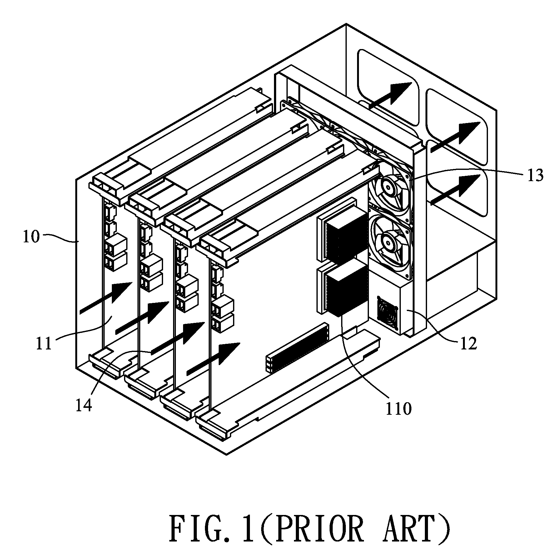
However, there will be problems if the chassis architecture disclosed above is applied to implement the personal cluster computer.
The narrow space(s) and unsmooth surfaces cause more serious turbulences, which will lead to wind noises.
However, a smaller fan with high speed also causes serious operation noises of high decibel.
Moreover, the narrow split spaces also cause problems while configuring the power distribution board (power switch), KVM switch (Keyboard / Video / Mouse switch), fan control board (fan switch), storage devices, network connection devices or other function modules in an optimal space arrangement.
That leads to additional problems, not only influencing the airflow 14 but increasing mechanical interferences while hanging hard drive tray(s) on the mainboard(s) 11.
The power distribution board, fan control board or other small circuit boards with specific functions has another issue.
Furthermore, above architecture can not provide sufficient expansion capability for a personal cluster computer.
That causes a crowded split space and the fastening issue for the graphic card.

Method used


Image

  • Chassis partition framework for personal cluster computer
  • Chassis partition framework for personal cluster computer
  • Chassis partition framework for personal cluster computer

Examples


first embodiment

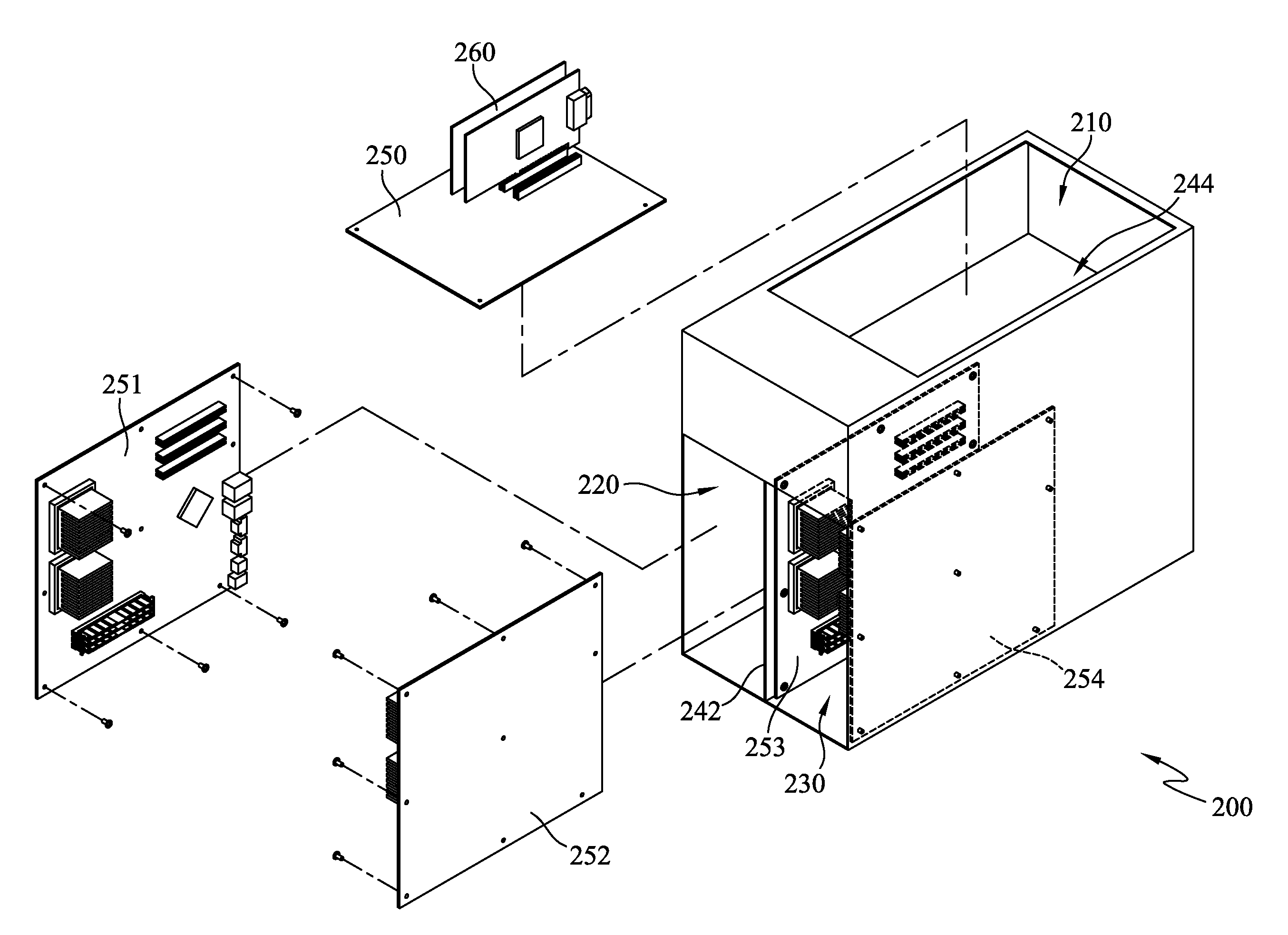
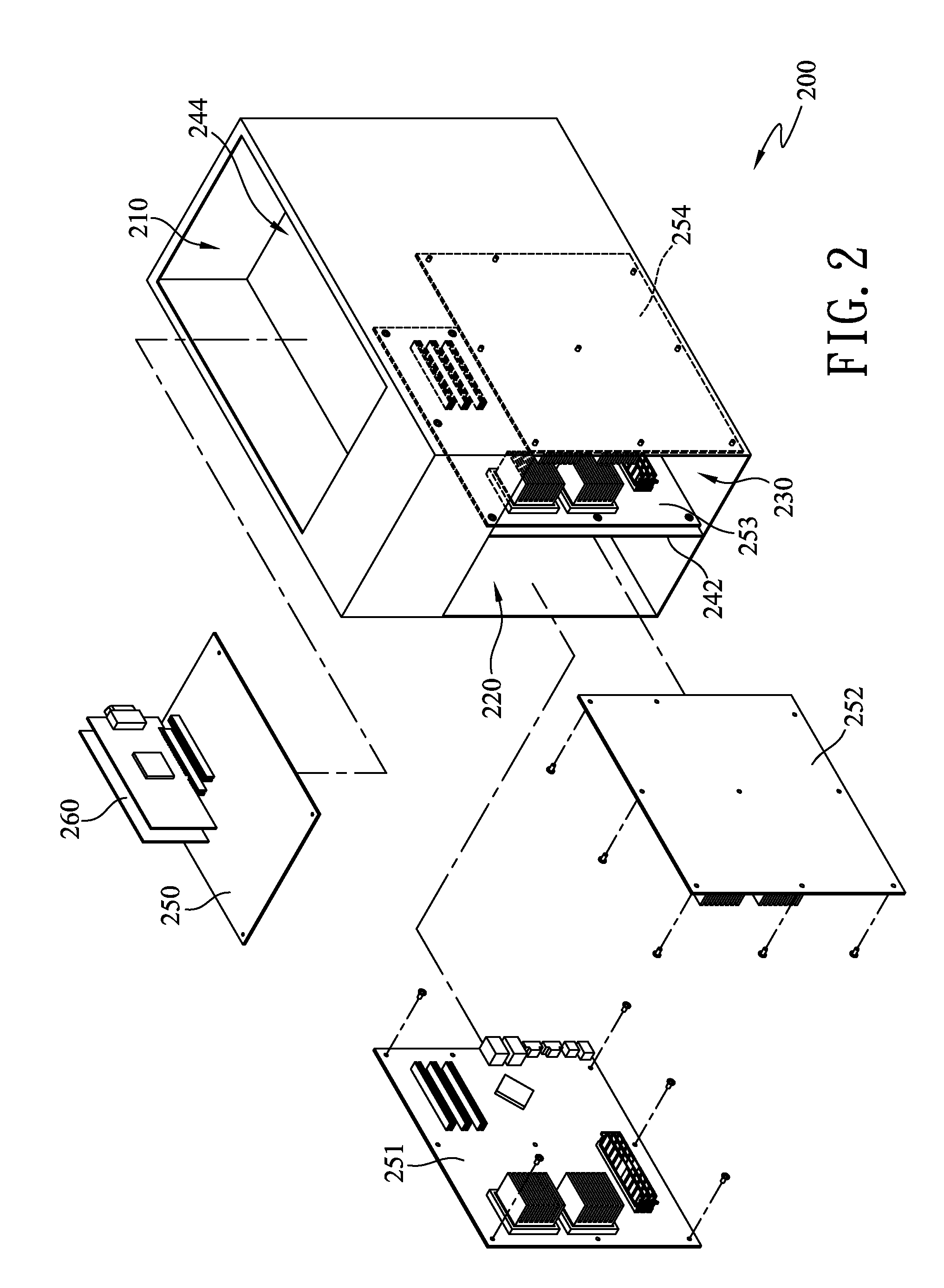
[0025]Please refer to FIG. 2. In the present invention, a chassis partition framework 200 provided for a personal cluster computer is in the shape of rectangular solid, which may be realized by frameworks and boards (both not marked). The chassis partition framework mainly includes a top chamber 210, a left chamber 220 and the right chamber 230, all in the shape of rectangular solid. By means of configuring a middle partition board 242 at the bottom, front-middle section of the chassis partition framework 200, the left and right chambers 220,230 may be divided accordingly. By configuring an upper partition board 244 horizontally at the upper section of the chassis partition framework 200, the top chamber 210 and the left / right chamber 220 / 230 may be divided. The middle partition board 242 and the upper partition board 244 may be complete boards or have hole(s) in various sizes.

[0026]The personal cluster computer to apply the chassis partition framework 200 of the present invention m...

second embodiment

[0033]Please refer to FIG. 3. In the present invention, the chassis partition framework 200 further includes four trays 311,312,313,314, each for configuring the first, second, third and fourth compute-node mainboards 251,252,253,254 respectively. Any type of sliding rail module (not shown) or its equivalent may be applicable to the top sides and / or the bottom sides of the left and right chambers 220,230, to allow the tray 311˜314 carrying the first, second, third and fourth compute-node mainboards 251˜254 and sliding into the left and right chambers 220,230 or sliding out. If necessary, the tray 311˜314 may have rail-relative structures at their tops or bottoms.

third embodiment

[0034]Please refer to FIG. 4. For clearer explanation, the head-node mainboard 250 and the upper partition board 244 have been removed. In the present invention, the chassis partition framework 200 further includes an openable left side-door 410 and an openable right side-door 420 for respectively configuring the first and fourth compute-node mainboards 251,252. Each of the left and right side-doors 410,420 has pivot sets 411, 421 at any position(s) on the two lateral sides of the chassis partition framework 200. One group of preferred locations are at the external sides of the left and right chambers 220,230 near the bottom, thereby enabling the left and right side-doors 410,420 to open and make the first and fourth compute-node mainboards 251,254 rotate to horizontal positions and facilitate serviceable tasks on the first and fourth compute-node mainboards 251,254. After the left / right side-doors 410,420 is opened, two openings (not shown / marked) formed at the two lateral sides of...


PUM


Abstract

A chassis partition framework is provided for configuring a personal cluster computer that has a head-node mainboard, a first compute-node mainboard, a second compute-node mainboard, a third compute-node mainboard and a fourth compute-node mainboard. The chassis partition framework mainly includes a top chamber, a left chamber and a right chamber. The top chamber is for configuring the head-node mainboard horizontally. The left and right chambers located under the top chamber are for vertically configuring the first and second compute-node mainboards and the third and fourth compute-node mainboards respectively in face-to-face alignment, with the second and third compute-node mainboards standing in back-to-back alignment. Therefore, the mechanical problems of the conventional blade-type personal cluster computer about heat-dissipation, noise-reduction, expansibility and space-arrangement may be improved through the chassis partition framework.

Description

BACKGROUND OF THE INVENTION[0001]1. Field of Invention[0002]The present invention relates to computer chassis framework, and more particularly to a chassis partition framework for a personal cluster computer.[0003]2. Description of the Related Art[0004]As shown in FIG. 1, a personal cluster computer in the prior art performs small-scale but high-complex clustering tasks under so-called “Blade” architecture. As illustrated, the front portion of the inner space of a chassis 10 is configured with plural mainboards (mother boards) 11, wherein all the mainboards 11 are spaced at intervals to split the front portion of the inner space of the chassis 10 into several narrow split spaces as airflow channels, as the common blade architecture. The lower half of the rear portion in the chassis 10 is configured with one or more power supply 12 that has dedicated fan(s); the upper half is configured with several main fans 13 as a major generation source for heat-dissipation airflow. The airflows ...

Claims


Application Information

Patent Timeline
Patent Type & Authority Patents(United States)
IPC IPC(8): H05K7/16
CPCG06F1/20G06F1/184
Inventor MCCLURE, JOHNLEE, CHUN-HUNG
Owner MITAC INT CORP
Learn More