
Anchor wedge configuration for tendon anchors

a wedge configuration and tendon technology, applied in the field of tendon anchoring systems, can solve the problems of structural concrete, inability to carry significant tensile loads, and insufficient use of concrete full potential, and achieve the effect of limiting the lateral compression of wedge segments

Active Publication Date: 2010-06-01
PRECISION HAYES INT INC
View PDF13 Cites 25 Cited by
  • Summary
  • Abstract
  • Description
  • Claims
  • Application Information

AI Technical Summary

Benefits of technology

"The invention is a wedge for a post tension anchor and a reinforcement system. The wedge has two segments that are placed on the tendon and have gripping elements on their interior surface. The wedge segments have a gap between their ends that is limited to prevent excessive compression. The reinforcement system includes an anchor plate with a tapered bore and the wedge segments with gripping elements and a compression limiting device that limits the lateral compression of the wedge segments. The technical effects of this invention are improved stability and durability of the post tension anchor and reinforcement of the tendon."

Problems solved by technology

On the other hand, structural concrete, though quite capable of carrying almost any compressive (vertical) load, is essentially unable to carry significant tensile loads.
Structures made from reinforced concrete may be built with load-bearing walls, but this configuration does not use the full potential of the concrete.
As a result of the new certification procedures, it has been determined that post tensioning anchoring devices known in the art fail certification testing in a substantial number of cases.
The steel alloys used in post tensioning anchoring devices are already developed to such an extent that improving the tensile strength of the anchoring devices themselves would be difficult and expensive.

Method used


Image

  • Anchor wedge configuration for tendon anchors
  • Anchor wedge configuration for tendon anchors
  • Anchor wedge configuration for tendon anchors

Examples


Embodiment Construction

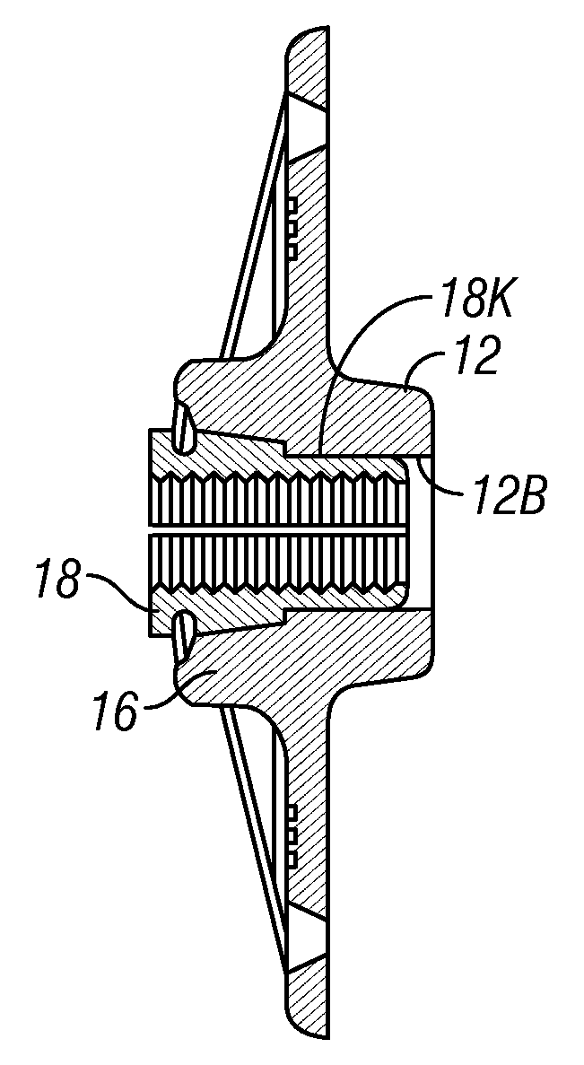
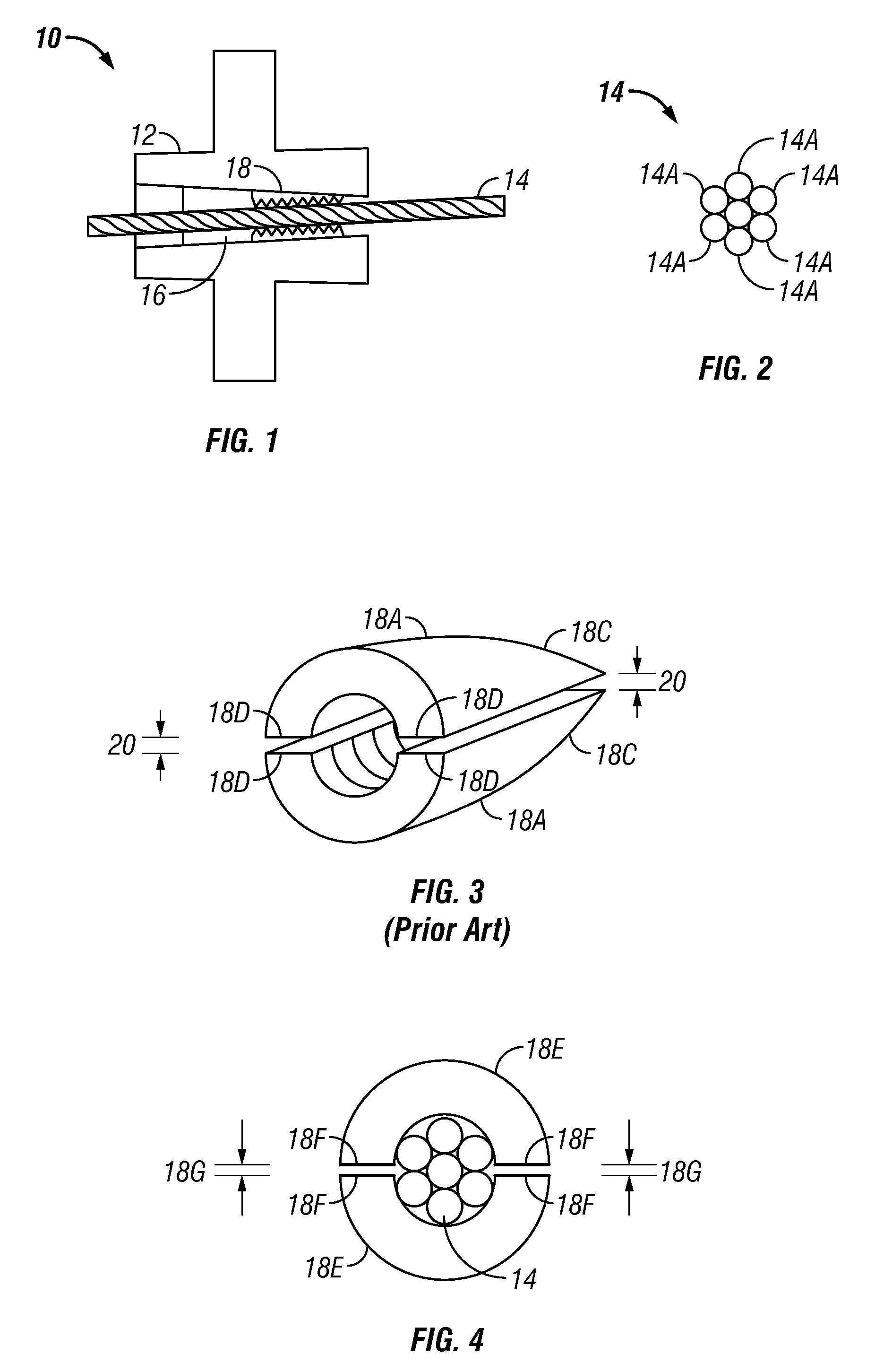
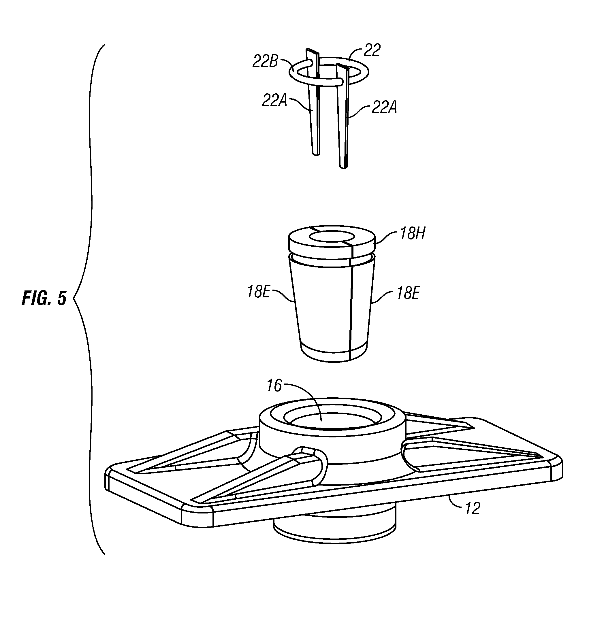
[0026]Generally, the invention includes tendon retaining wedge segments and / or anchor plates formed to have particular features as will be explained below in more detail. Some embodiments of wedge segments and / or anchor plates according to the invention are intended to be used with post-tension anchor systems, and for purposes of illustrating the invention, a post tension anchor system will be explained. However, wedge segments and / or anchor plates according to various aspects of the invention may be used with any other application for a tendon system, including, without limitation, the various applications described in the Background section herein.

[0027]An assembled post-tension anchor system and post-tension tendon are shown generally in cross section in FIG. 1. The anchor system 10 includes load transfer device called an anchor plate or anchor base 12, usually cast or forged from a ductile metal. The anchor plate 12 is adapted to be cast into or otherwise affixed to a concrete m...


PUM

PropertyMeasurementUnit
outer diameteraaaaaaaaaa
axial lengthaaaaaaaaaa

Abstract

A wedge for a tendon retaining anchor includes at least two circumferential wedge segments adapted to be placed on an exterior of a tendon. The wedge segments have an exterior surface adapted to cooperate with a receiving bore of a load transfer device and an interior surface having gripping elements thereon. A circumferential dimension of the wedge segments is selected so that a total uncompressed gap between circumferential ends of the wedge segments when the segments are applied to an exterior surface of the tendon is at most about 2.4 times a height of the gripping elements. In another aspect, a tendon retaining system includes an anchor having a wedge receiving bore and wedge segments adapted to cooperate with the wedge receiving bore. The wedge segments include gripping elements on an interior surface thereof. The system includes a device adapted to limit lateral compression of the wedge segments.

Description

CROSS-REFERENCE TO RELATED APPLICATIONS[0001]Not applicable.STATEMENT REGARDING FEDERALLY SPONSORED RESEARCH OR DEVELOPMENT[0002]Not applicable.BACKGROUND OF THE INVENTION[0003]1. Field of the Invention[0004]The invention relates generally to the field of tendon anchoring systems. More particularly, in one aspect the invention relates to post tension systems for reinforcing concrete structures.[0005]2. Background Art[0006]The present invention is described herein primarily with reference to post-tension anchoring devices and systems. However, the invention can be used in any application requiring retention of a tendon within an anchorage or other device which transfers tension from the tendon to another structure. Such applications include, without limitation, prestress chucks and couplers, post tensioning applications for bridges, post tension jacks, cable stay wedges, post tensioning applications for roads, bridge tie-backs, mine shaft wall and roof retainers, wall retainers and w...

Claims


Application Information

Patent Timeline
Patent Type & Authority Patents(United States)
IPC IPC(8): E04C5/08
CPCE04C5/127E04C5/122
Inventor HAYES, NORRIS O.DRAGINIS, RANDY
Owner PRECISION HAYES INT INC
Learn More