Adaptive processing method of clutter rejection in a phased array beam pattern

a phased array and beam pattern technology, applied in the field of can solve the problems of actual phased array radar systems, failure of individual failure of transmit and receive modules, etc., and achieve the effect of minimizing any best fit errors

Active Publication Date: 2010-06-01
RAYTHEON CO
View PDF7 Cites 19 Cited by
  • Summary
  • Abstract
  • Description
  • Claims
  • Application Information

AI Technical Summary

Benefits of technology

[0008]It is a further object of this invention to provide such a method which determines the element weightings to generate a desired antenna beam pattern with low side lobes for effective clutter rejection.

Problems solved by technology

The cost of such a system is typically driven by sensitivity which is a function of the number and design of the active transmit and receive modules.
Actual phased array radar systems, however, often have failures of the individual transmit and receive modules and / or include transmit and receive modules which are not used to produce the main beam.
As a result, the transmitted Cosecant-squared antenna pattern may have high side lobes which degrade effective clutter rejection.

Method used


Image

  • Adaptive processing method of clutter rejection in a phased array beam pattern
  • Adaptive processing method of clutter rejection in a phased array beam pattern
  • Adaptive processing method of clutter rejection in a phased array beam pattern

Examples


Embodiment Construction

[0024]Aside from the preferred embodiment or embodiments disclosed below, this invention is capable of other embodiments and of being practiced or being carried out in various ways. Thus, it is to be understood that the invention is not limited in its application to the details of construction and the arrangements of components set forth in the following description or illustrated in the drawings. If only one embodiment is described herein, the claims hereof are not to be limited to that embodiment. Moreover, the claims hereof are not to be read restrictively unless there is clear and convincing evidence manifesting a certain exclusion, restriction, or disclaimer.

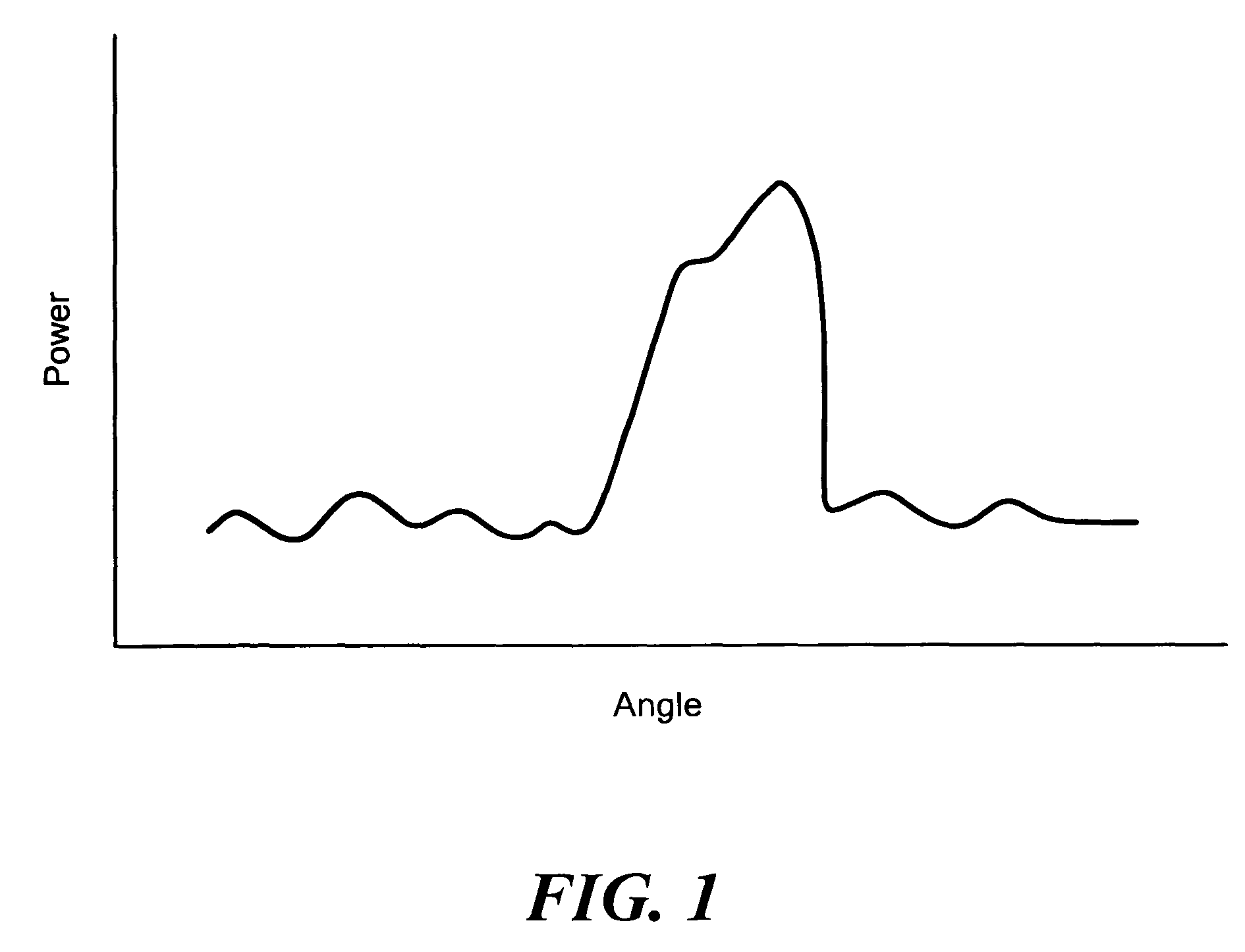
[0025]FIG. 1 shows an idealized amplitude distribution of a two-dimensional phased array Cosecant-squared pattern with low side lobes. Such an idealized pattern is not always realized due to the failure of transmit and receive modules in the two-dimensional array, the geometry of the array, and / or transmit and receive modul...


PUM


Abstract

An adaptive processing method of and system for clutter rejection in a phased array beam pattern. The amplitude distribution of the transmit elements of a two-dimensional phased array is determined. A desired pattern with low side lobes for a linear array is synthesized. The amplitude distribution of the transmit elements of the two-dimensional phased array is compared with the synthesized pattern. Select elements of the two-dimensional array are disabled to best fit the determined amplitude distribution of the transmit elements of the two-dimensional phased array to the synthesized beam pattern. Phase only pattern synthesis is performed to produce a desired two-dimensional beam pattern with low side lobes to minimize any best fit errors.

Description

FIELD OF THE INVENTION[0001]This subject invention relates to phased array radar systems.BACKGROUND OF THE INVENTION[0002]A typical phased array radar system includes a number of transmit and receive modules each driven at a certain amplitude and phase. A beam steering generator sets the amplitude and phase of each transmit module. In this way, the radiation pattern is reinforced in a certain direction and suppressed in undesired directions.[0003]The cost of such a system is typically driven by sensitivity which is a function of the number and design of the active transmit and receive modules. Phased array radars provide a spatial degree of freedom to shape the transmitted beams. Fully focused beams can be generated for high sensitivity missions and shaped and spoiled beams can be generated for lower sensitivity missions. The well-known Cosecant-squared beam pattern provides many of the advantages of sensitivity time control to avoid saturation and short pulse operation to minimize ...

Claims


Application Information

Patent Timeline
Patent Type & Authority Patents(United States)
IPC IPC(8): H01Q3/26
CPCG01S7/414H01Q21/22H01Q3/2605G01S2013/0254
Inventor CHANG, KAICHIANGKENNEDY, WILLIAM
Owner RAYTHEON CO
Why Eureka
Try Eureka