Microwave and millimeterwave radar sensors

a radar sensor and microwave technology, applied in the field of microwave and millimeterwave radar sensors, can solve the problems of poor rf performance, overly simple, overly complex mmw radar subsystem rf implementation, etc., and achieve the effects of low cost, accurate modulation, and low phase nois

Active Publication Date: 2010-06-15
HONEYWELL INT INC
View PDF7 Cites 32 Cited by
  • Summary
  • Abstract
  • Description
  • Claims
  • Application Information

AI Technical Summary

Benefits of technology

[0006]The present invention provides a low cost means to achieve the needed sensitivity of the microwave or MMW radar sensors with low phase noise and accurate modulation at the lowest possible cost of signal generation and signal processing. The proposed system has the advantage being scaled in size from one sensor to many sensors, all served by a common control and signal processing system.

Problems solved by technology

The RF implementation of the MMW Radar subsystems has either been overly complex (frequency multiplication systems) or overly simple with poor RF performance (MMW Oscillator directly connected to an antenna and modulated).
Both systems generate very high phase noise and varying modulation characteristics over time and environmental changes.
Both factors significantly degrade the performance of the resulting system.

Method used


Image

  • Microwave and millimeterwave radar sensors
  • Microwave and millimeterwave radar sensors
  • Microwave and millimeterwave radar sensors

Examples


Embodiment Construction

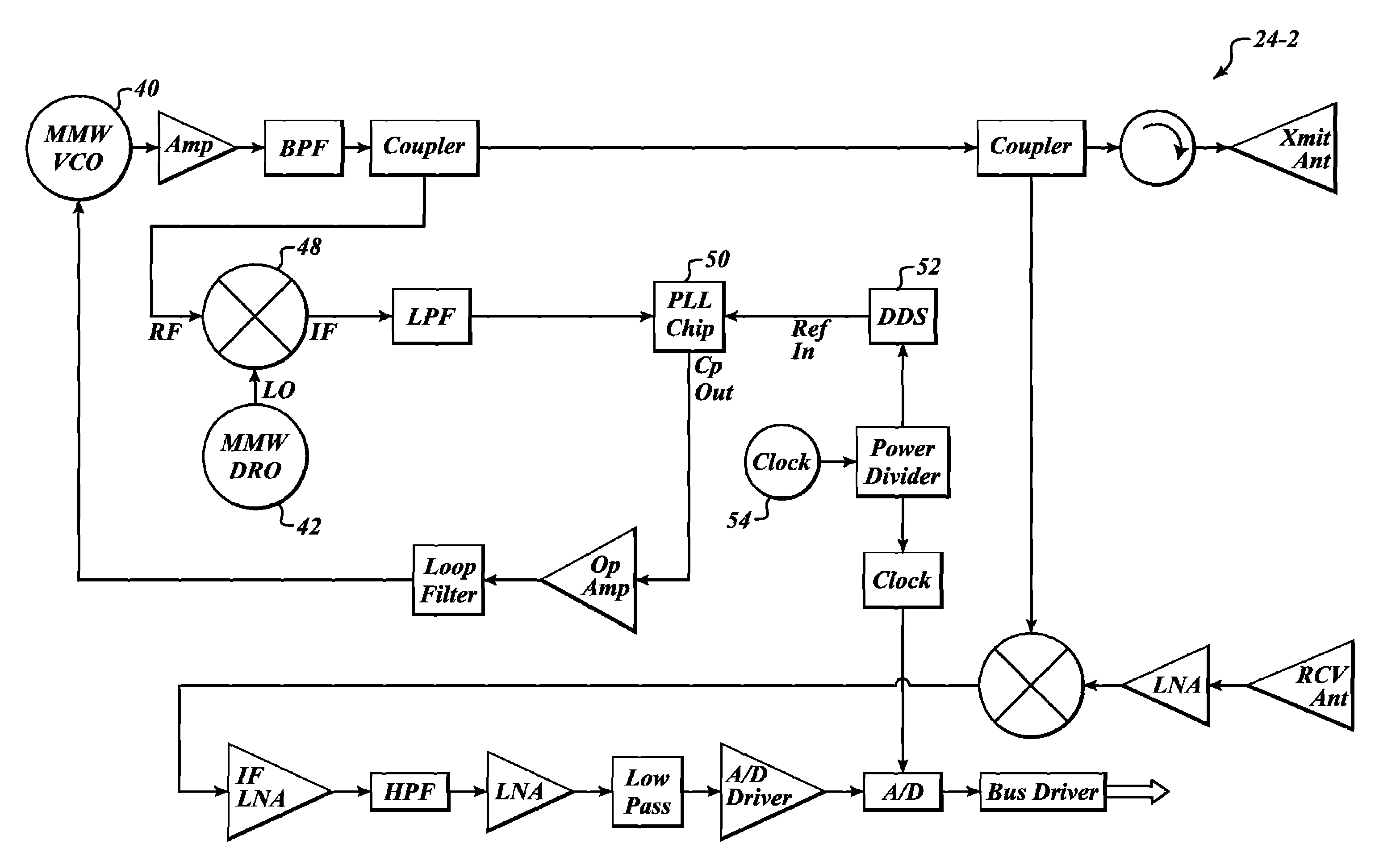
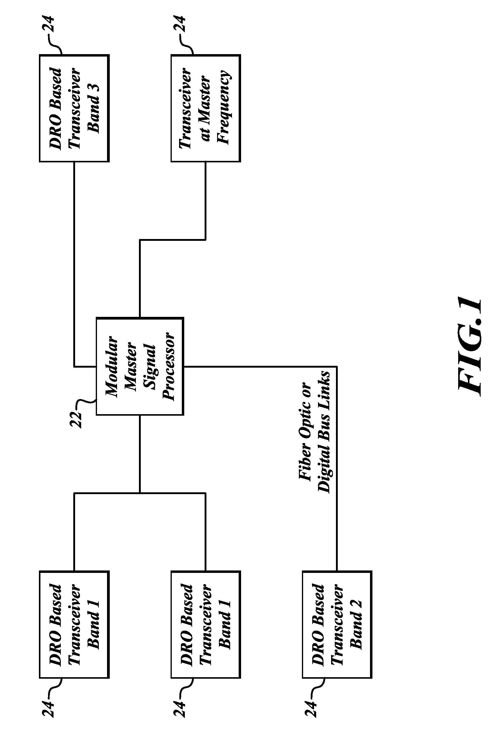
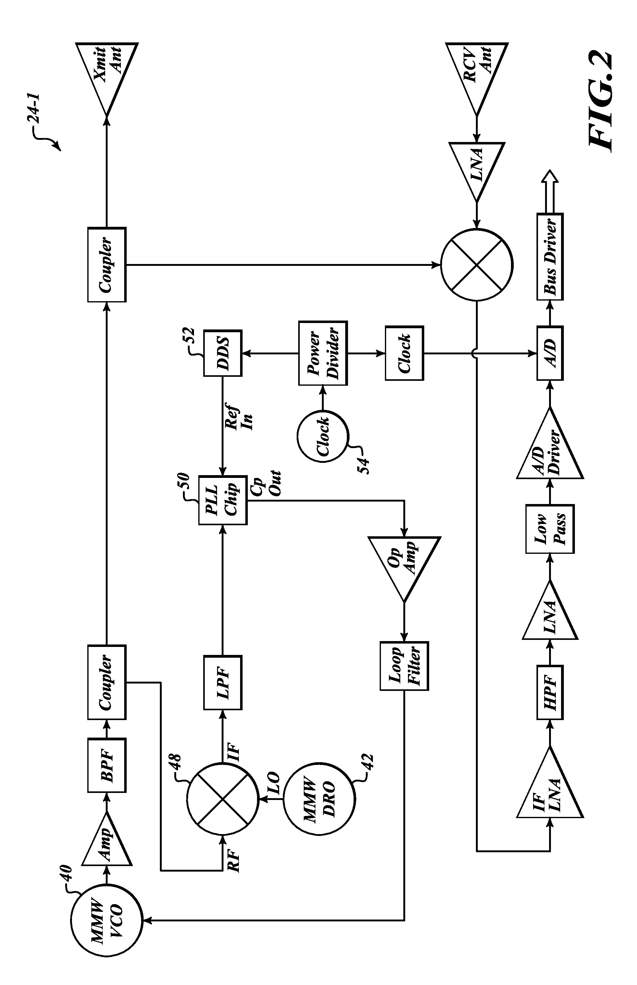
[0012]As shown in FIG. 1, the present invention provides a system 20 that includes a master signal processor 22 in signal communication with one or more radar components 24. The radar components 24 translate an operating frequency to Microwave or millimeterwave (MMW) range by mixing it with an “open loop” oscillator that operates at MMW frequencies that offers frequency stability over time, temperature and vibration, such as a Dielectric Resonator Oscillator (DRO) (example DROs are produced by Honeywell Inc.). The DRO provides excellent frequency stability over time, temperature and load conditions with very low phase noise. An array of radar components 24 are mounted to a vehicle or building and are controlled by the processor 22. The processor 22 determines if any of the radar components 24 have sensed any objects and outputs that determination to an operator.

[0013]The processor 22 provides control signals for altering the modulation or antenna scanning at each radar component 24....


PUM


Abstract

A radar sensor system and method for vehicles. An example radar system includes a processor, a plurality of transceivers having antenna(e). The antenna of the transceivers are located at various points around the vehicle. The transceivers include receive and transmit electronics that are in signal communication with the corresponding antenna. The transmit electronics output radar signals via the antenna. The transmit electronics include a voltage controlled oscillator (VCO), a dielectric resonator oscillator (DRO), a phase locked loop (PLL) component and a direct digital synthesizer (DDS). The receive electronics receive from the antenna any radar reflections corresponding to the outputted radar signals and send signals associated with the radar reflections to the processor. The processor generates output signals based on the signals received from the plurality of transceivers.

Description

BACKGROUND OF THE INVENTION[0001]There are multiple automotive, marine and aviation applications where small, low cost millimeterwave (MMW) radar sensors are distributed around a vehicle to provide functions, such as adaptive cruise control, anti-collision warning, brake applications, parking, marine threat detection or marine docking guidance.[0002]Many developers have created low cost MMW sensors, particularly for the automotive marketplace where production numbers can be in the 100,000s. Most use modulation that is either FM / CW or UltraWideband. In the typical application, each sensor provides its own modulation and signal processing in a single package. Adding more sensors requires adding complete radar and signal processing / control systems to each location and then combining data from each in yet another computing platform. This duplicates many functions.[0003]The RF implementation of the MMW Radar subsystems has either been overly complex (frequency multiplication systems) or ...

Claims


Application Information

Patent Timeline
Patent Type & Authority Patents(United States)
IPC IPC(8): G01S13/93G01S13/931
CPCG01S7/023G01S7/35G01S13/87G01S13/931G01S13/343G01S2013/9321G01S7/0232G01S7/0236
Inventor VACANTI, DAVID C.
Owner HONEYWELL INT INC
Why Eureka
Try Eureka