
Insert for nucleus implant

Active Publication Date: 2010-06-22
DEPUY SPINE INC (US)
View PDF24 Cites 51 Cited by
  • Summary
  • Abstract
  • Description
  • Claims
  • Application Information

AI Technical Summary

Problems solved by technology

One of the primary hurdles an NDR device has to overcome is the ability to stay within the annulus of the disc.
Another issue is that the containment wall of the NDR is often a degenerated annulus that has existing fissures or will develop fissures in which the NDR device can expulse over time.

Method used


Image

  • Insert for nucleus implant
  • Insert for nucleus implant
  • Insert for nucleus implant

Examples


Embodiment Construction

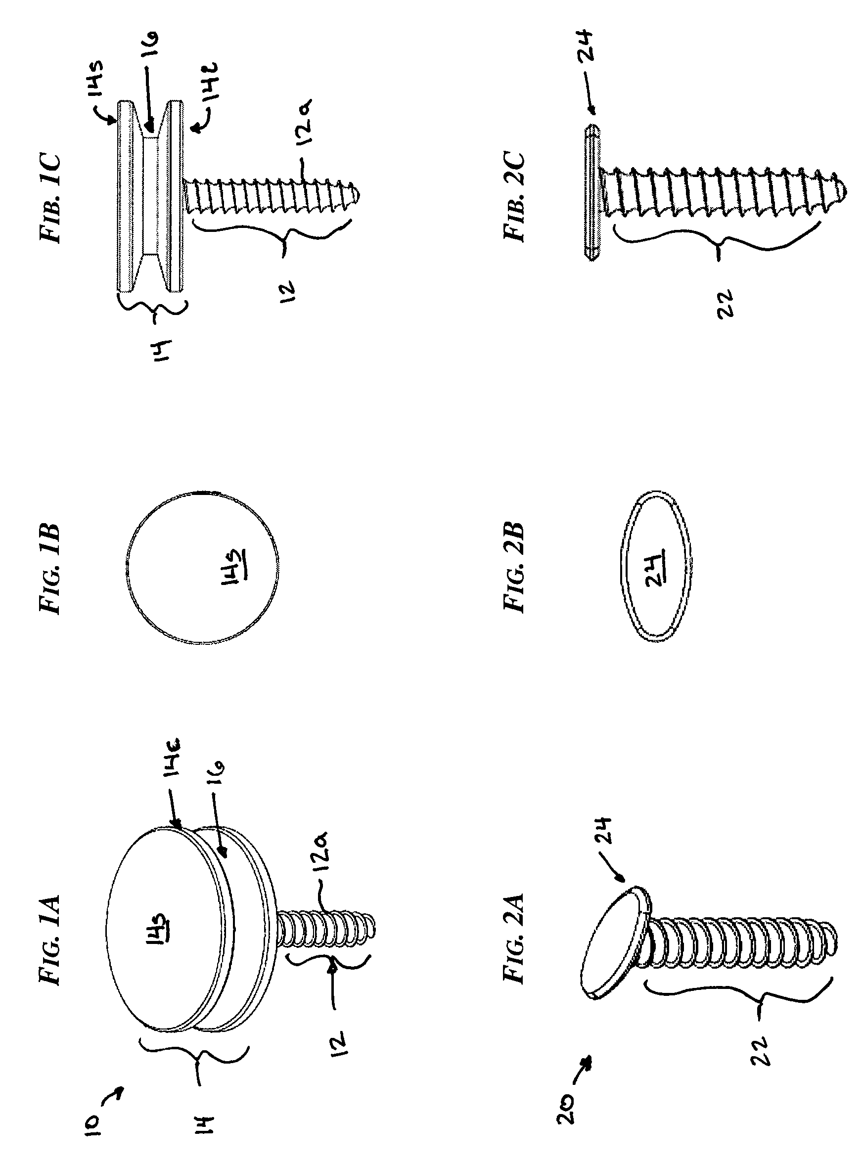
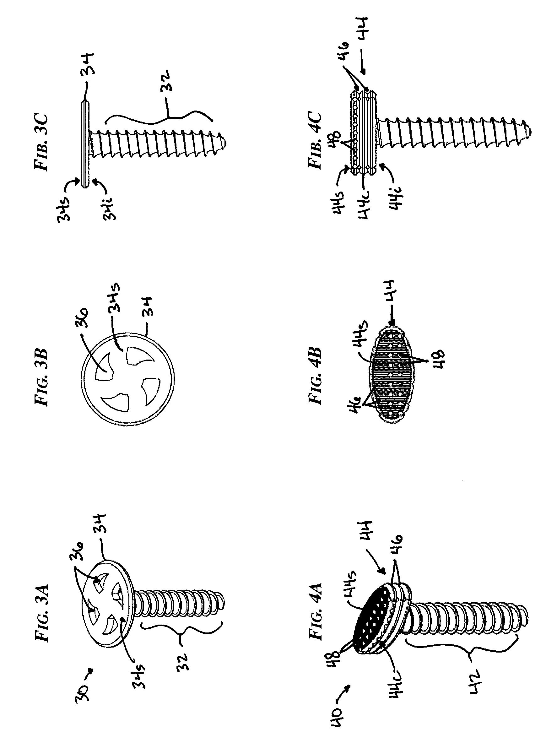
[0039]Certain exemplary embodiments will now be described to provide an overall understanding of the principles of the structure, function, manufacture, and use of the devices and methods disclosed herein. One or more examples of these embodiments are illustrated in the accompanying drawings. Those of ordinary skill in the art will understand that the devices and methods specifically described herein and illustrated in the accompanying drawings are non-limiting exemplary embodiments and that the scope of the present invention is defined solely by the claims. The features illustrated or described in connection with one exemplary embodiment may be combined with the features of other embodiments. Such modifications and variations are intended to be included within the scope of the present invention.

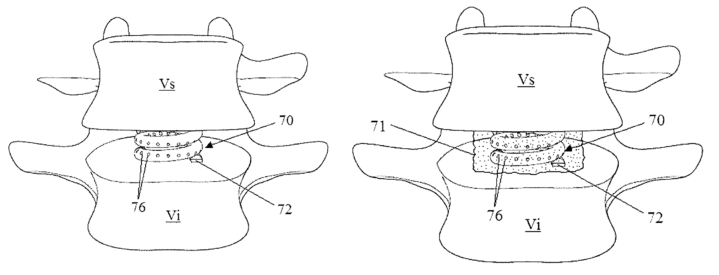
[0040]The present invention generally provides methods and devices for replacing a nucleus of a spinal disc, and in particular for preventing nucleus disc replacement expulsion. The nucleus ...


PUM


Abstract

Methods and devices are provided for replacing a nucleus of a spinal disc, and in particular for preventing nucleus disc replacement expulsion. The nucleus of a spinal disc can be removed from the annulus by forming a small opening in the annulus. Once the nucleus is removed, one or more insert devices can be implanted within the annulus of a spinal disc and they can be mated to one or both endplates of the adjacent vertebrae. The insert(s) is configured to interact with a nucleus disc replacement implant to prevent expulsion of the implant from the annulus.

Description

FIELD OF THE INVENTION[0001]The present invention relates to methods and devices for replacing a nucleus of a spinal disc.BACKGROUND OF THE INVENTION[0002]A spinal disc is composed of two main parts, a gel-like inner portion called the nucleus pulposus, and a tough outer portion called the annulus fibrosus. The annulus is similar to a radial tire surrounding the nucleus. In a healthy disc, the nucleus is contained, and for the most part, centered within layers of the annulus, allowing for even distribution of pressures thereby providing cushioning to the adjacent vertebrae surrounding the disc.[0003]An artificial disc (also called a disc replacement, disc prosthesis or spine arthroplasty device) is a device that is implanted into the spine to imitate the functions of a natural disc (carry load and allow motion). There are many artificial disc designs classified into two general types: total disc replacement (TDR) and nucleus disc replacement (NDR). As the names imply, with a TDR, al...

Claims


Application Information

Patent Timeline
Patent Type & Authority Patents(United States)
IPC IPC(8): A61F2/44
CPCA61F2/442A61B17/0642A61F2230/0093A61B2017/0648A61F2002/30125A61F2002/30289A61F2002/30299A61F2002/30462A61F2002/30566A61F2002/30583A61F2002/30772A61F2002/30841A61F2002/3085A61F2002/30878A61F2002/30909A61F2002/444A61F2002/4495A61F2210/0085A61F2220/0075A61F2230/0008A61F2230/0091A61B2017/0647
Inventor ZARDA, BRETT R.O'NEIL, MICHAEL J.HALL, MARK T.
Owner DEPUY SPINE INC (US)
Learn More