

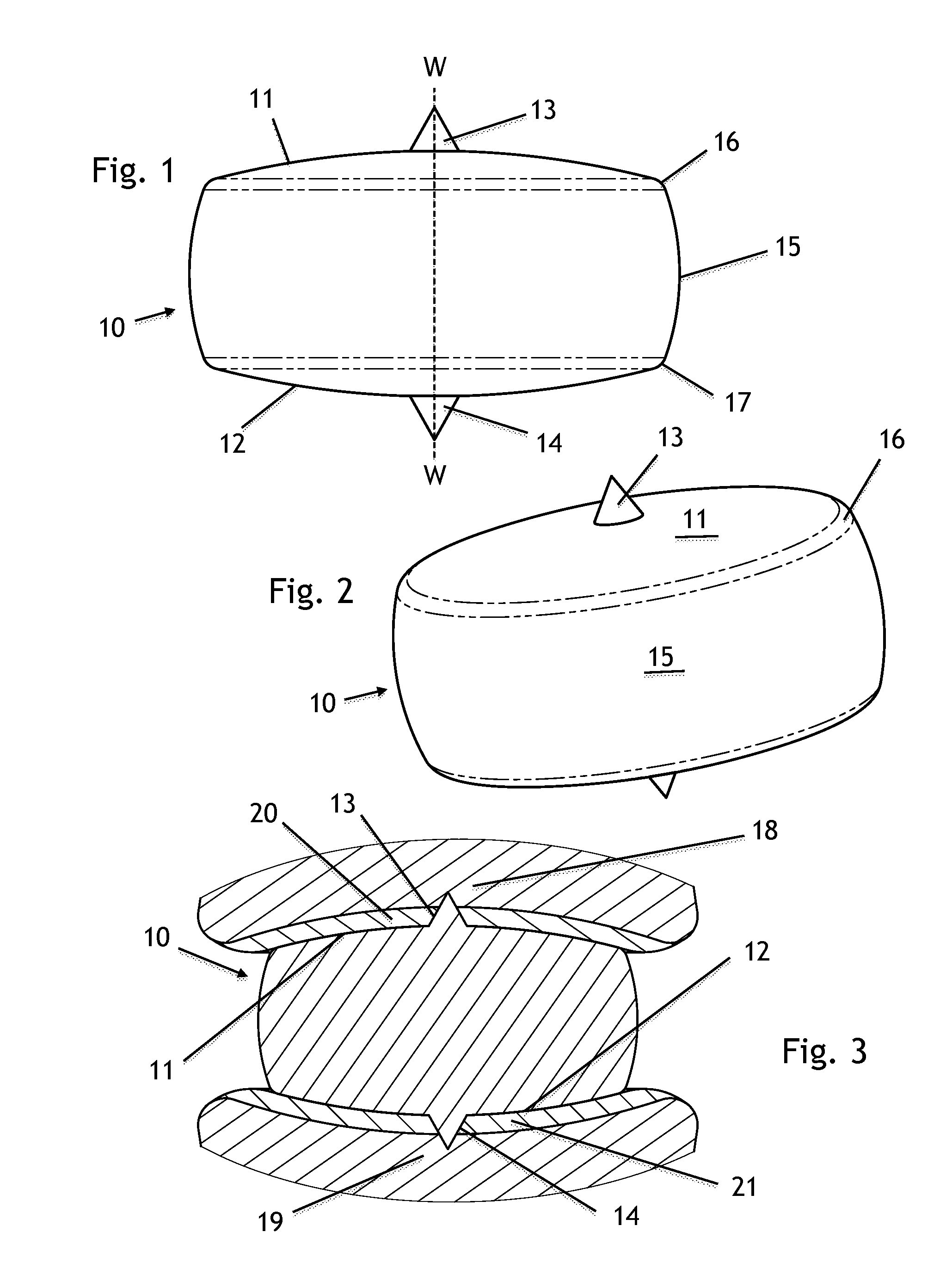
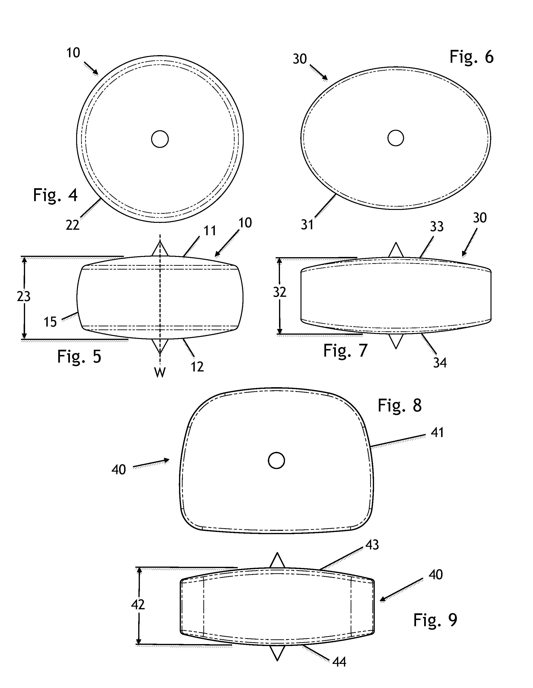
Unitary Spinal Disc Implant
a unitary disc and disc technology, applied in the field of unitary disc implants, can solve the problems of disc replacements that may also need to be revised, compromise vertebral endplates, poor choice of materials for articular wear bearings, and/or inadequate long-term wear characteristics between device sub-components, etc., to preserve or restore near-normal motion, limit flexion and rotation
- Summary
- Abstract
- Description
- Claims
- Application Information
AI Technical Summary
Benefits of technology
Problems solved by technology
Method used
Image

Examples
embodiment 50
[0178]In some embodiments of the implant, the first bearing surface and the first protrusion are polished articulating surfaces as illustrated in the non-limiting examples of FIGS. 28 and 29. In other embodiments, the second bearing surface and the second protrusion are polished articulating surfaces as illustrated in the non-limiting examples of FIGS. 14 and 15. In this embodiment 50, the central protrusion 51, resides on only one surface of the implant verses protrusions 13 and 14 on both surfaces (FIG. 11). Typically this protrusion would be on the inferior surface. However, it could also be located on the superior surface. The surface 52 opposite the surface with the protrusion 51 is sufficiently smooth and polished in order to articulate against the native cartilage or endplate, while minimizing wear. This embodiment of one central protrusion on either the inferior or superior surface, but not both, can be incorporated with any of the previously mentioned perimeter geometries (...
embodiment 60
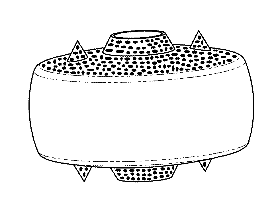
[0198]Referring now to FIGS. 16-18, an embodiment 60, comprises truncated conic protrusions 61 and 62 respectively located at the center or the approximate center of superior and inferior surfaces 68, 69 respectively, similar to protrusions 13 and 14 (FIG. 1) except that they have a larger base perimeter (64, 65) and truncated top (66, 67) to accommodate a thru-hole 63 sized to allow for bone or tissues ingrowth, or graft material that is intended to provide additional capture, further minimizing the potential for expulsion. The perimeter or cross section geometry of the thru-hole can either be a circle, preferred for manufacturing reasons, or any other geometry. The size of the thru-hole 63 is a size that accommodates and promotes bone or tissue ingrowth. This size, generally, will typically have a sectional area range equivalent to diameters ranging from 2.0 mm to 10.0 mm, but may be larger or smaller. The surface finish of the thru-hole 63 may be textured to provide better adhesi...
embodiment 70
[0199]Another embodiment 70, represented by FIGS. 19-21, comprises a protrusion 71 with a blind hole 72 on just one surface 75 that can be either the superior or inferior surface of the implant. The geometry of the protrusion is similar to 61 and 62 previously mentioned (FIG. 17) and the average sectional width 73 of blind hole 72 is similar to previously mentioned thru-hole 63. The depth 74 of the blind hole may at a minimum be about 0.5 mm, and at a maximum depth being approximately 1.0 mm from the point of breaking through the opposite surface 76. The surface finish of the blind hole 72 may be textured to provide better adhesion properties for ingrowth of tissue. Additionally, the hole may be inversely tapered to promote a better anchoring reservoir that would resist pullout of the anchoring materials under natural loading conditions. This embodiment can be incorporated with any of the previously mentioned perimeter geometries (22, 31 and 41) with superior and inferior surfaces p...
PUM
| Property | Measurement | Unit |
|---|---|---|
| lordotic angle | aaaaa | aaaaa |
| lordotic angle | aaaaa | aaaaa |
| lordotic angle | aaaaa | aaaaa |
Abstract
Description
Claims
Application Information