
Toner cartridge, process cartridge, image cartridge, and image forming apparatus to which those cartridges are attachable

a technology cartridges, which is applied in the direction of electrographic process apparatus, instruments, optics, etc., can solve the problems of image forming apparatus, toner running out, and image forming apparatus

Active Publication Date: 2010-06-29
KONICA MINOLTA INC
View PDF16 Cites 16 Cited by
  • Summary
  • Abstract
  • Description
  • Claims
  • Application Information

AI Technical Summary

Benefits of technology

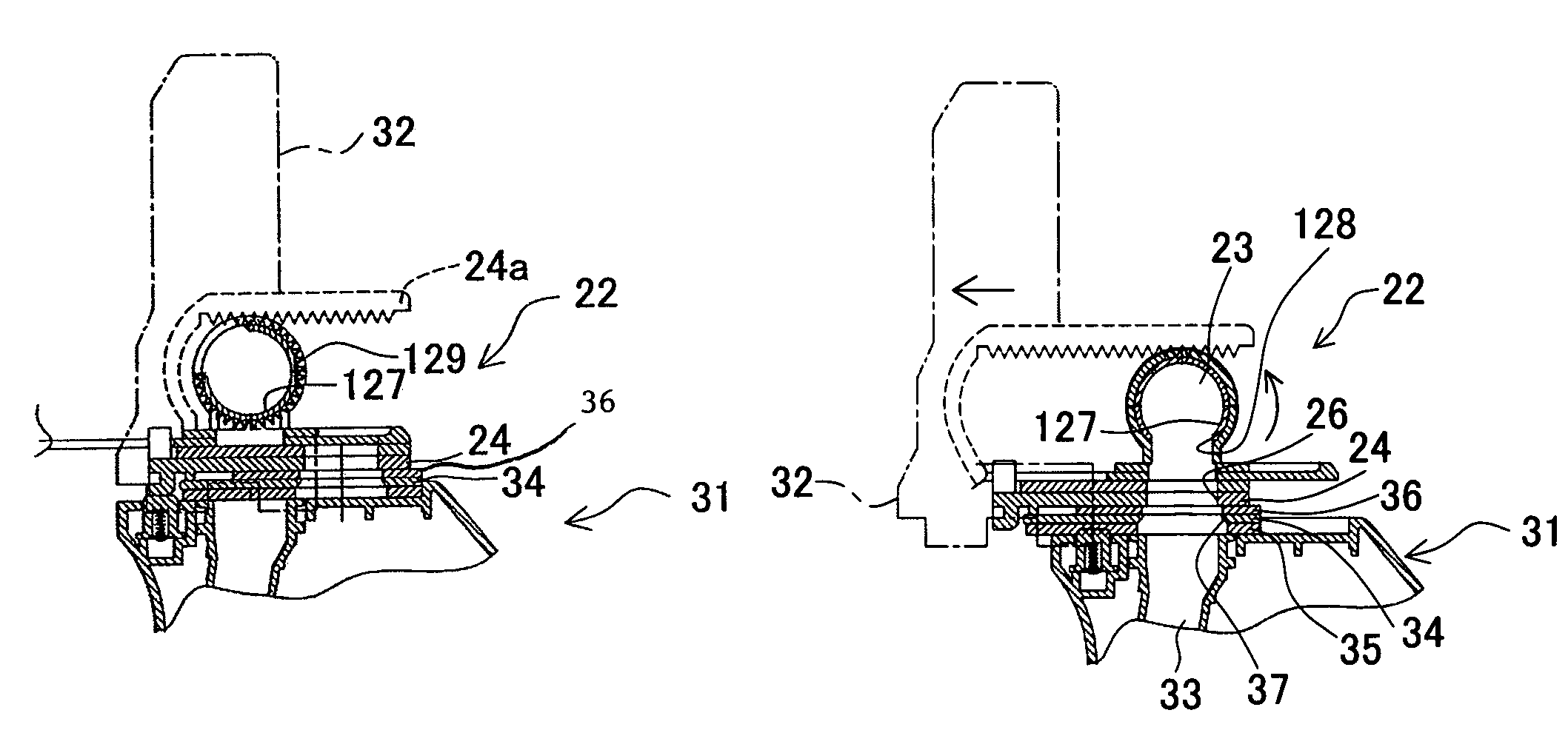
The present invention provides a solution to prevent toner leakage from conventional image forming apparatuses. The invention includes a toner cartridge, a process cartridge, and an image forming apparatus. The toner cartridge has a shutter that can be opened and closed to prevent toner leakage. The process cartridge includes a cylindrical shutter and a gear, and a rotation blocking member that prevents the shutter from being opened when the process cartridge is attached. The invention prevents toner leakage from both the toner cartridge and the process cartridge, making it easier for users to attach the cartridges without making the surrounding area dirty. The invention also provides an improved design for the attachment of the toner cartridge and process cartridge to the image forming apparatus.

Problems solved by technology

However, the above-mentioned conventional image forming apparatuses had the following problems.
Therefore, in the case a user stops attachment or detachment operation in the middle and tries it again from the beginning or in the case a user cannot carry out attachment and detachment operation smoothly, toner can possibly run out from the half-opened shutter.
Furthermore, the image forming apparatus directed to the Publication No. 07-152239 cannot carry out image formation if a user forgets to open the slide shutter after a toner cartridge is attached.
Furthermore, since no shutter is provided at its toner hopper side, toner can possibly scatter in the middle of attachment and detachment operation.
However, proper operation was not easy for a user who rarely carries out the operation.

Method used


Image

  • Toner cartridge, process cartridge, image cartridge, and image forming apparatus to which those cartridges are attachable
  • Toner cartridge, process cartridge, image cartridge, and image forming apparatus to which those cartridges are attachable
  • Toner cartridge, process cartridge, image cartridge, and image forming apparatus to which those cartridges are attachable

Examples


first embodiment

[0076]A first embodiment will be described in detail with reference to the accompanying drawings. The first embodiment applies the present invention to a color printer of which toner housing portion and process portion are provided as separable units.

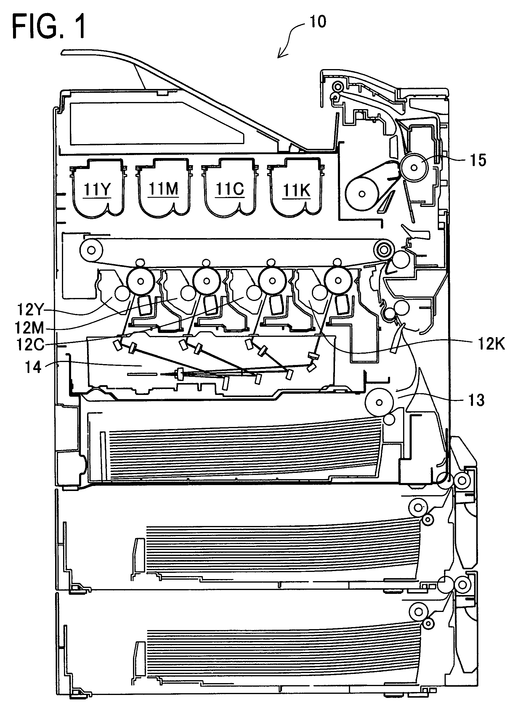
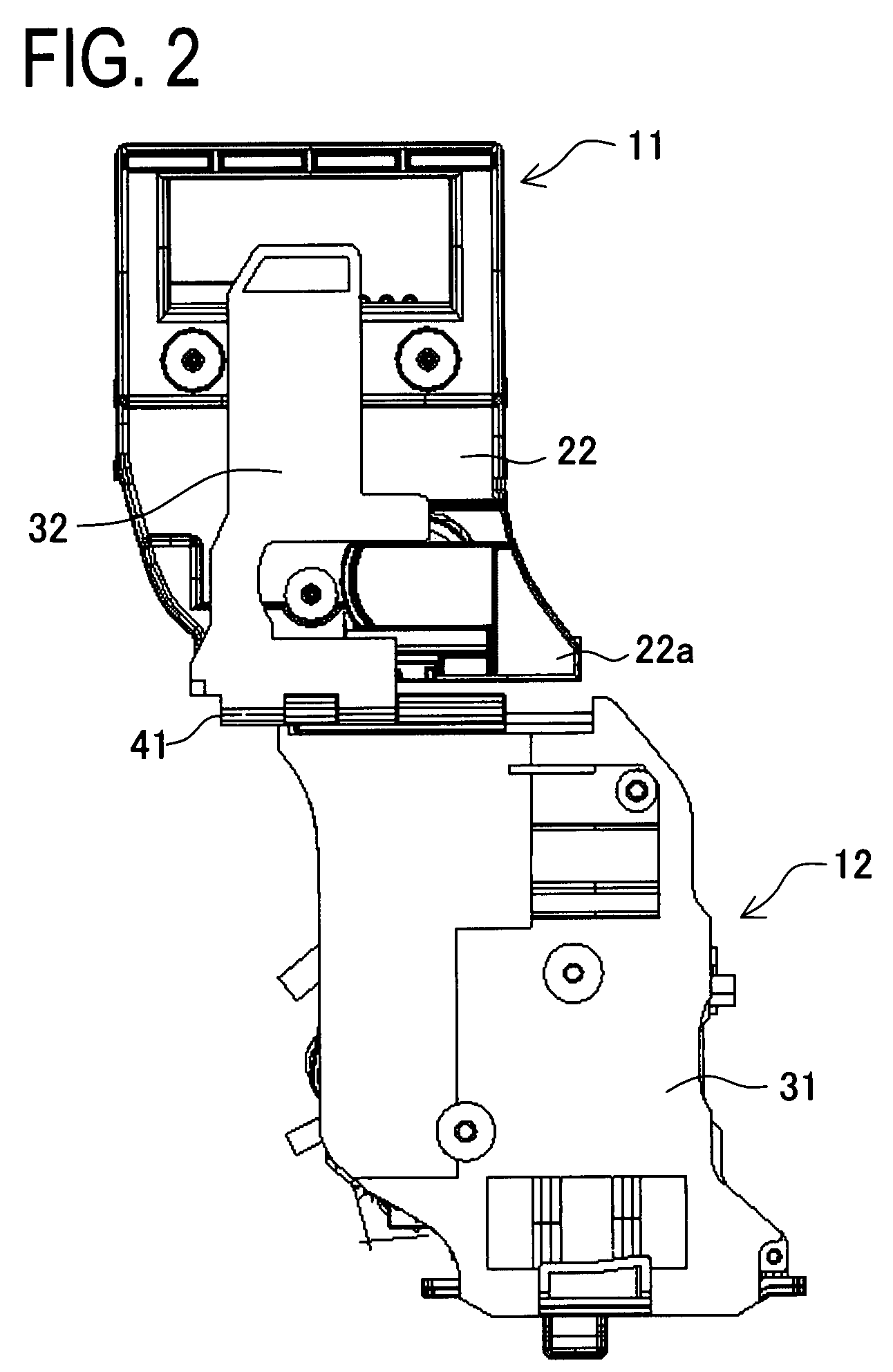
[0077]As schematically shown in FIG. 1, a color printer 10 is an image forming apparatus which forms a color image using four colors (Y, M, C, and K) of toner. The color printer 10 includes toner cartridges 11Y, 11M, 11C, and 11K and process cartridges 12Y, 12M, 12C, and 12K corresponding to respective four colors. As shown in FIG. 1, units are arranged in a row in a left and right direction, in other words, a front and rear direction of a unit corresponds to a depth direction of the apparatus when it is inserted in there. Since structure of the toner cartridges 11Y, 11M, 11C and 11K are identical, they will be simply indicated as toner cartridges 11 without indicating suffixes Y, M, C, or K, hereafter. Also, since structure of the proc...

second embodiment

[0104]Next, a second embodiment will be described in detail with reference to the accompanying drawings. In the second embodiment, a cylindrical shutter is additionally provided on the toner cartridge 11 of the first embodiment and the cylindrical shutter can be opened and closed together with other shutters. As to composing members equivalent to the first embodiment, same numerals are assigned to them and descriptions on them will be omitted.

[0105]Relating to a color printer directed to the second embodiment, as shown in FIG. 17 and FIG. 18, a cylindrical shutter 63 is provided on a communicating passage 62 of its toner cartridge 61. The cylindrical shutter 63 is a cylindrical member and a communicating hole 64 is formed on a part of it. The cylindrical shutter 63 is fitted in an inner face of the communicating passage 62 rotatably. Furthermore, in FIG. 17, a right end portion of the cylindrical shutter 63 is sealed and a gear 65 is formed at the periphery thereon. The gear 65 is p...

third embodiment

[0108]A third embodiment will be described in detail with reference to the accompanying drawings. In the third embodiment, shutter structure of the toner cartridge 11 and the process cartridge 12 directed to the first embodiment is slightly changed. In the present embodiment, a slide-type shutter is not employed. As to composing members equivalent to the first and second embodiments, same numerals are assigned to them and descriptions on them will be omitted.

[0109]Relating to a color printer directed to the third embodiment, as shown in FIG. 22, a cylindrical shutter 72 is provided on a communicating passage of the toner cartridge 71. A communicating hole 73 is formed on the cylindrical shutter 72. Furthermore, a gear 74 is formed on one end face of the cylindrical shutter 72. A part of the gear 74 protrudes downward from a lower face of a case of the toner cartridge 71, in FIG. 22. The toner cartridge 71 has a stopper 75 which is to get engaged with one of teeth of the gear 74. The...


PUM


Abstract

A toner cartridge and a process cartridge, individually, have a shutter which makes sliding movement by opening and closing their toner inlet and toner outlet. When those cartridges are attached to a color printer and fixed together by a fixing lever, the shutters of both cartridges and the fixing lever can move together as one. When they make sliding movement together, both of the shutters are opened and toner supply becomes available. There are thus realized a toner cartridge, a process cartridge, an imaging cartridge, and an image forming apparatus to which those cartridges are attachable, all of which can prevent toner leakage from both a toner housing portion and a process portion and enables even an unaccustomed user to attach each cartridge without making surroundings dirty.

Description

CROSS-REFERENCE TO RELATED APPLICATIONS[0001]This application is based upon and claims the benefit of priority from the prior Japanese Patent Applications Nos. 2006-042766 and 2006-048328 filed on Feb. 20, 2006 and Feb. 24, 2006, respectively, the entire contents of which are incorporated herein by reference.BACKGROUND OF THE INVENTION[0002]1. Field of the Invention[0003]The present invention relates to an electrophotographic type image forming apparatus and various cartridges which are attached to and detached from the apparatus. More particularly, it relates to a toner cartridge for housing toner, a process cartridge including a process portion, e.g. a developing apparatus or the like, an imaging cartridge including a toner cartridge and a process cartridge therein, and an image forming apparatus to which the above cartridges are attachable.[0004]2. Description of the Related Art[0005]Conventionally, in an electrophotographic type image forming apparatus, a developing apparatus in...

Claims


Application Information

Patent Timeline
Patent Type & Authority Patents(United States)
IPC IPC(8): G03G15/08
CPCG03G21/1832G03G15/0886G03G15/0875G03G15/0879G03G2215/0692G03G2221/183
Inventor NAKAGAMI, HIDEKAZU
Owner KONICA MINOLTA INC
Learn More