

Child seat
a child seat and seat belt technology, applied in the field of child seats, can solve the problems of infant seat belt not fitting adults of vehicles, production cost rise,
- Summary
- Abstract
- Description
- Claims
- Application Information
AI Technical Summary
Benefits of technology
Problems solved by technology
Method used
Image

Examples
first embodiment
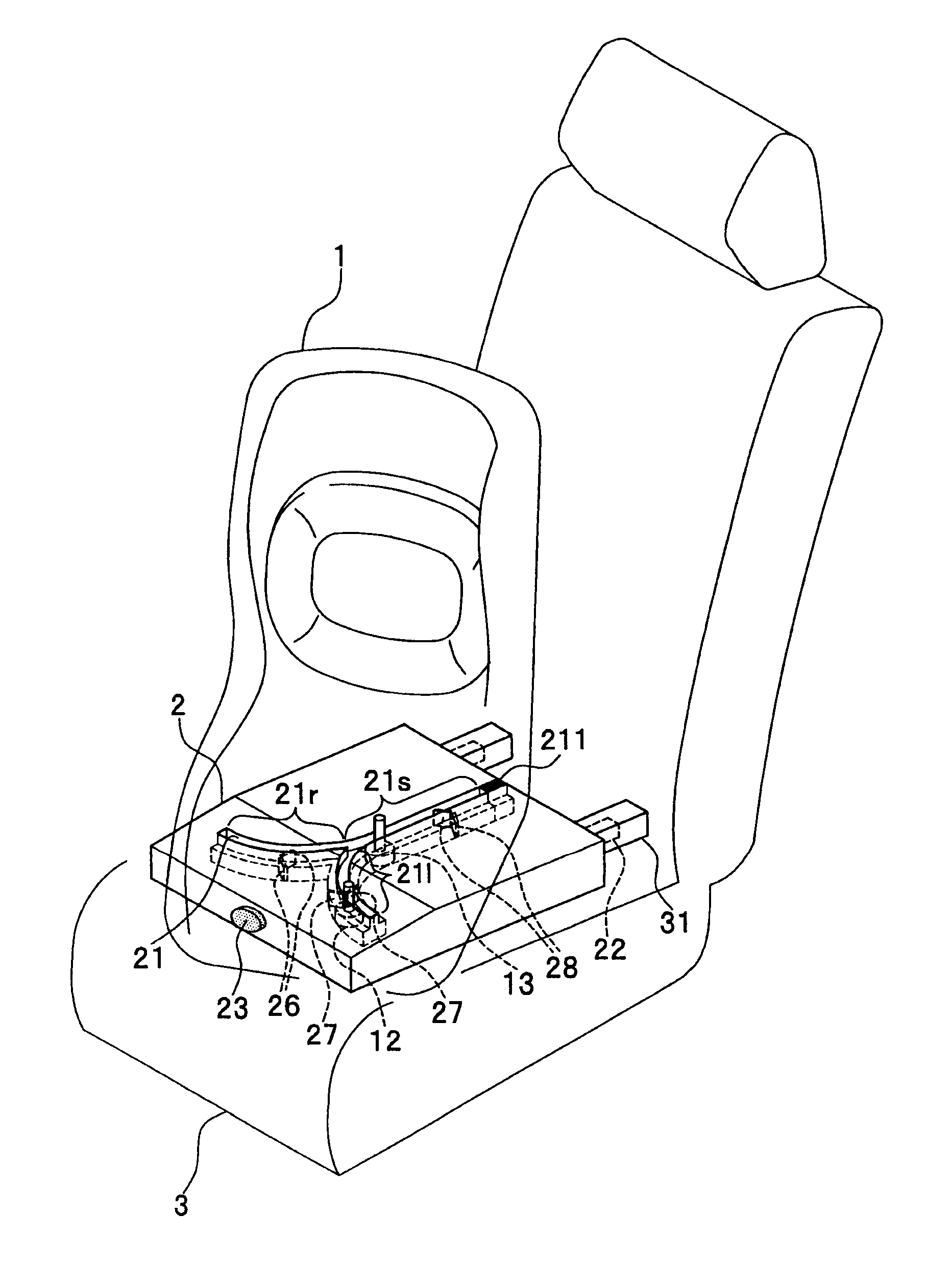
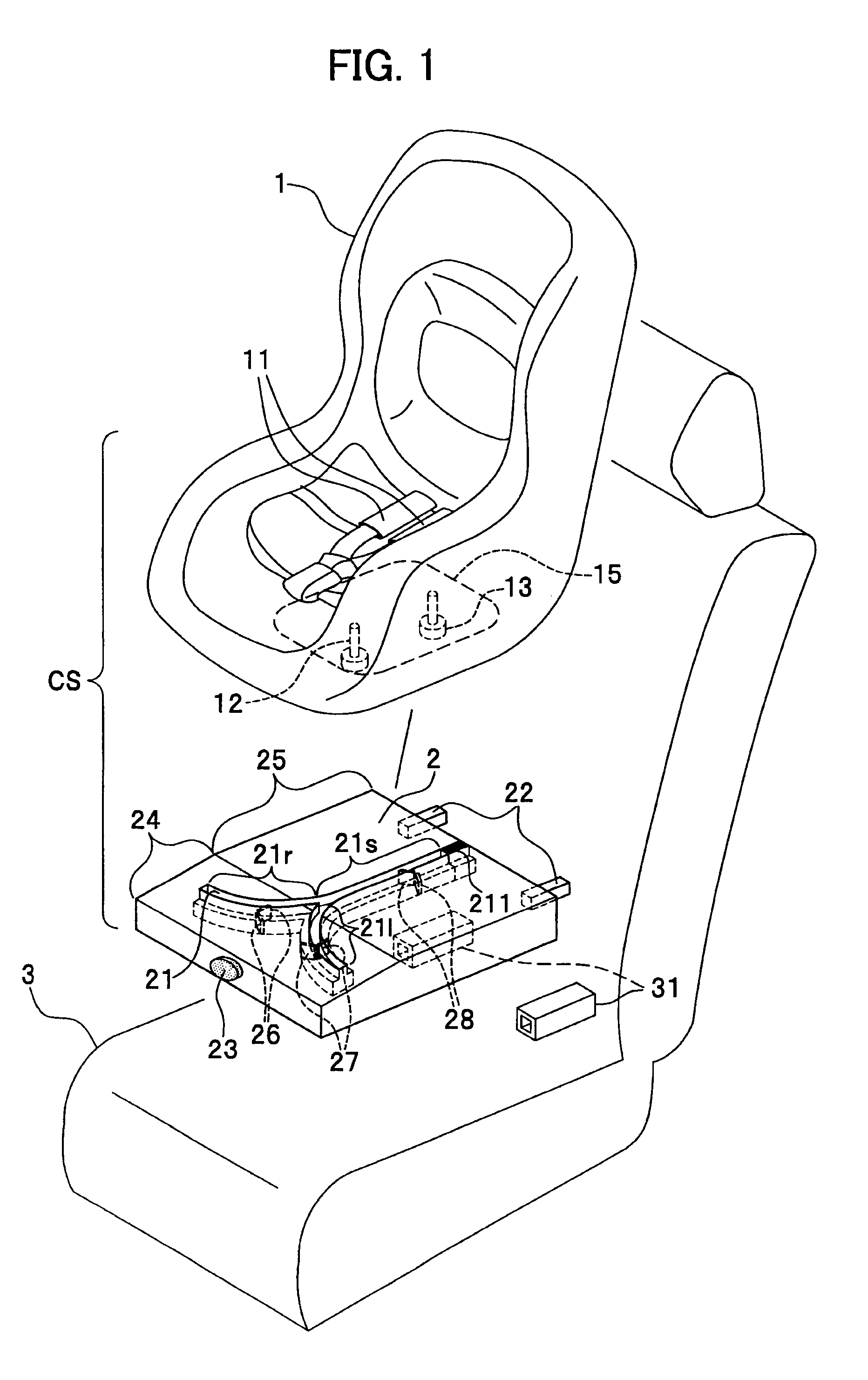
[0023]FIG. 1 is an exploded perspective view of an entire configuration including a child seat according to the first embodiment. The child seat CS comprises a child seat body 1 and a base platform 2. A vehicle seat 3 is, for example a rear seat (only a part is shown) of a car. The vehicle seat 3 has two female engagement parts 31 to fix the base platform 2. There are two female engagement parts 31, but only one of them may be mentioned in the following description, since the structure of the child seat CS is symmetrical. Likewise, for other paired components in symmetrical relation, only one of them may be mentioned. In FIG. 1, a left near side front is “front (forward)”, and a right far side is “rear (backward)”.
[0024]The child seat body 1 comprises seat belts 11 on a sitting part. The child seat body 1 further comprises a front guided member 12 and a rear guided member 13 arranged along a centerline of a bottom face 15 which is nearly flat. For example, the front guided member 12...
second embodiment
[0051]The child seat CS (hereinafter, “CS” is omitted) in the second embodiment will be described below with reference to FIG. 5. FIG. 5 is a structural perspective view showing a base platform of a child seat according to a second embodiment. In the figure, the child seat body 1 and the vehicle seat 3 are not shown, because they are similar to those of the first embodiment.
[0052]In comparison with the base platform 2 of the first embodiment, as for the base platform 2a, the same reference character is given to the same component, and thus a duplicate description is omitted. In addition, in FIG. 5, the male engagement part 22 and the locking mechanism which is similar to the lock member 26-28 are not shown.
[0053]As shown in FIG. 5, in the base platform 2a, a shape of a curved portion of the guide groove 21a is different from that of the guide groove 21 of the first embodiment. A curved portion divided into two ways at a spot “R2” is formed of a part of the circle having a center as ...
third embodiment
[0057]The child seat according to the third embodiment will be described below with reference to FIG. 6. FIG. 6 is a structural perspective view showing a base platform of a child seat according to a third embodiment. In FIG. 6, the child seat body 1 and the vehicle seat 3 are not shown, because they are similar to those of the first embodiment.
[0058]In comparison with the base platform 2 of the first embodiment, as for the base platform 2b, the same reference character is given to the same component, and thus a duplicate description is omitted. In addition, in FIG. 6, the male engagement part 22 and the locking mechanism which is similar to the lock member 26-28 are not shown.
[0059]As shown in FIG. 6, in the base platform 2b, a curved portion of a guide groove 21b includes a circle (curved portion 21bl, 21br) and a straight portion 21bs′ which is extended from a straight portion 21bs of the guide groove 21b, and serves as a diameter of the circle.
[0060]With the base platform 2b, in...
PUM
 Abstract
Description
Claims
Application Information