
Window assembly manufacturing method and window pane
a manufacturing method and window pane technology, applied in the direction of transportation and packaging, catheter, other domestic objects, etc., can solve the problems of easy deviation of adhesive strength, difficulty in adjusting the thickness of the adhesive layer, so as to achieve the same thickness and drying time, easy removal, and simplified adhesive application work
Patent Information
- Authority / Receiving Office
- US · United States
- Patent Type
- Patents(United States)
- Current Assignee / Owner
- Publication Date
- 2010-07-13
- Estimated Expiration
- Not applicable · inactive patent
Smart Images
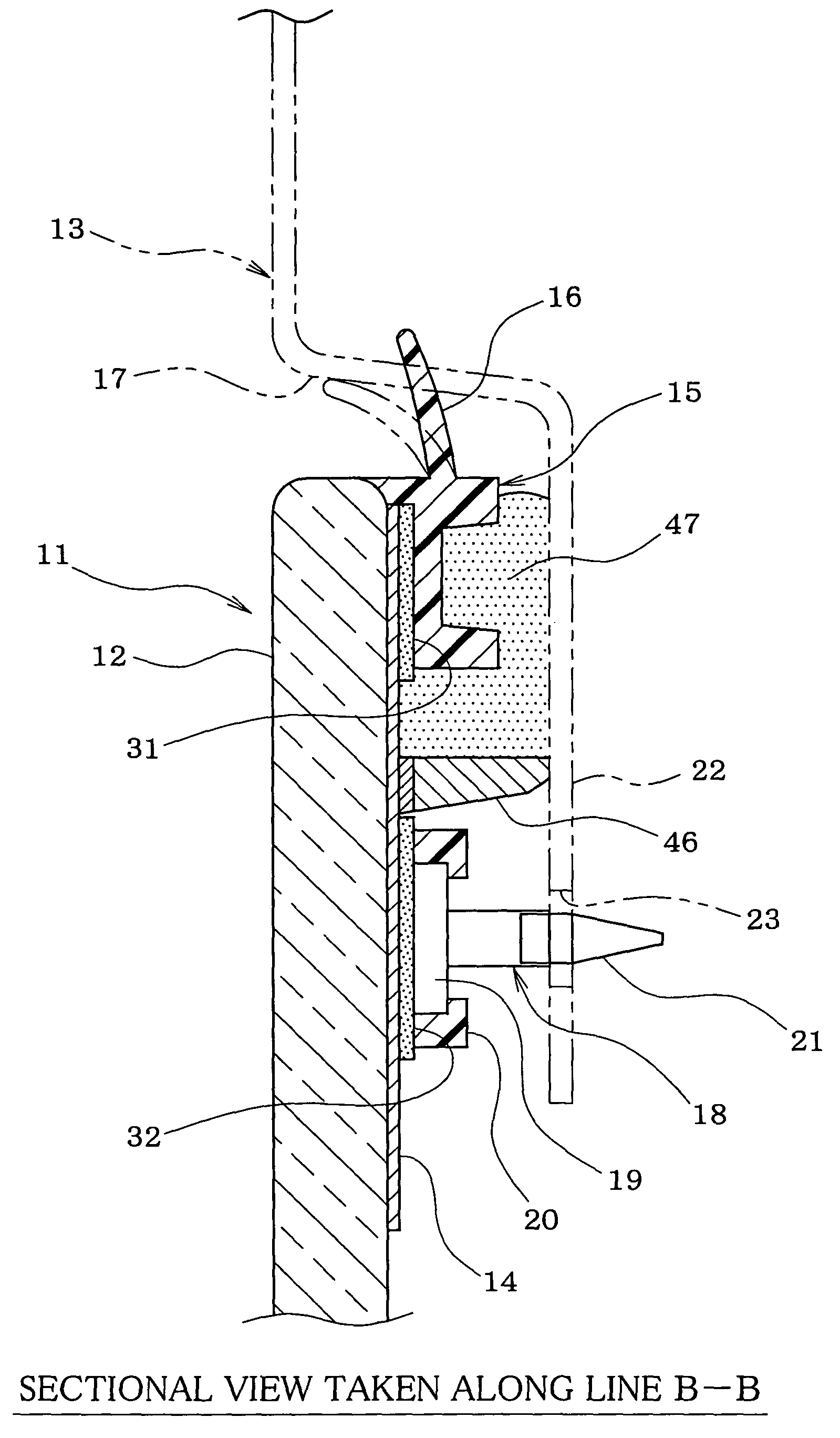
Figure 1 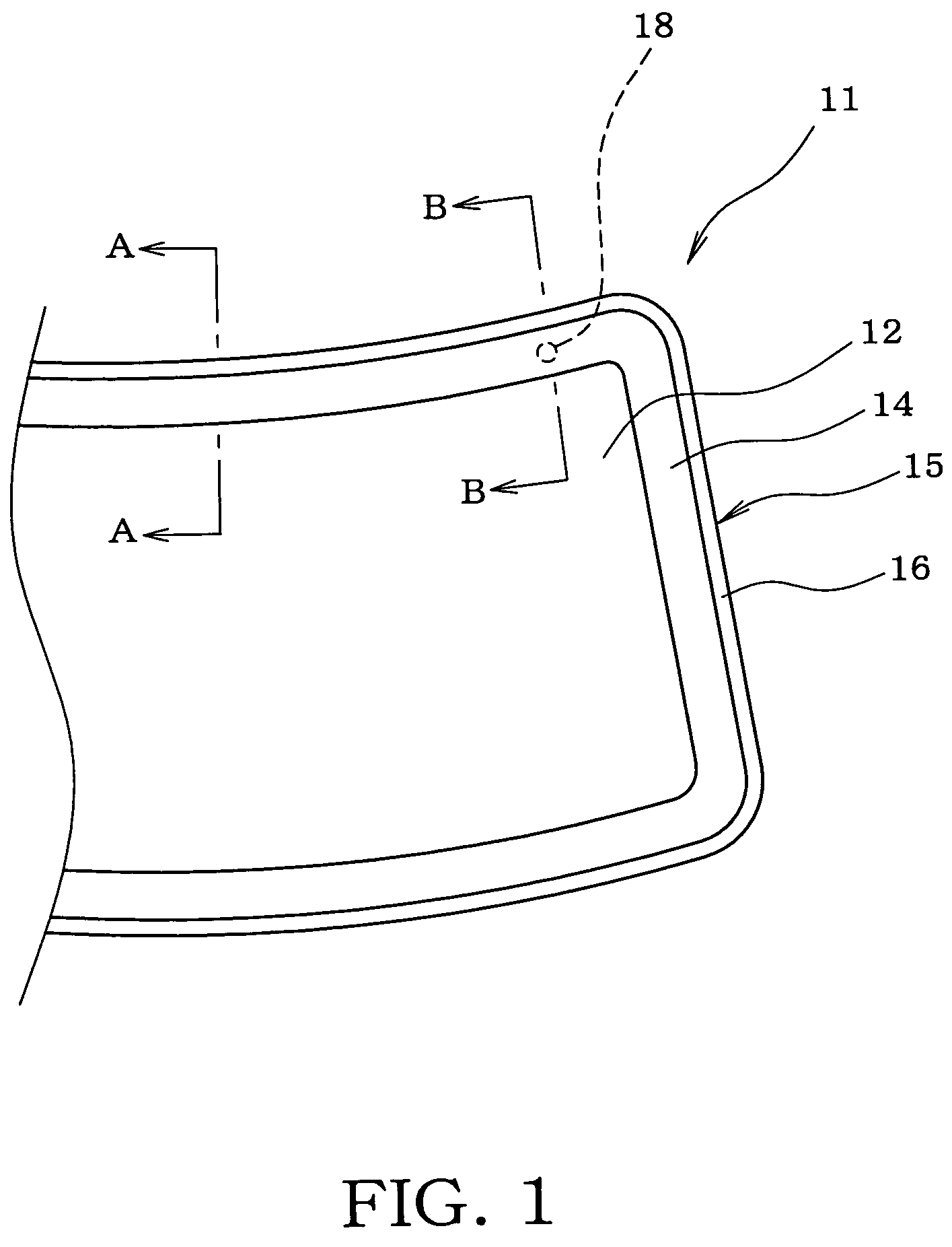
Figure 2 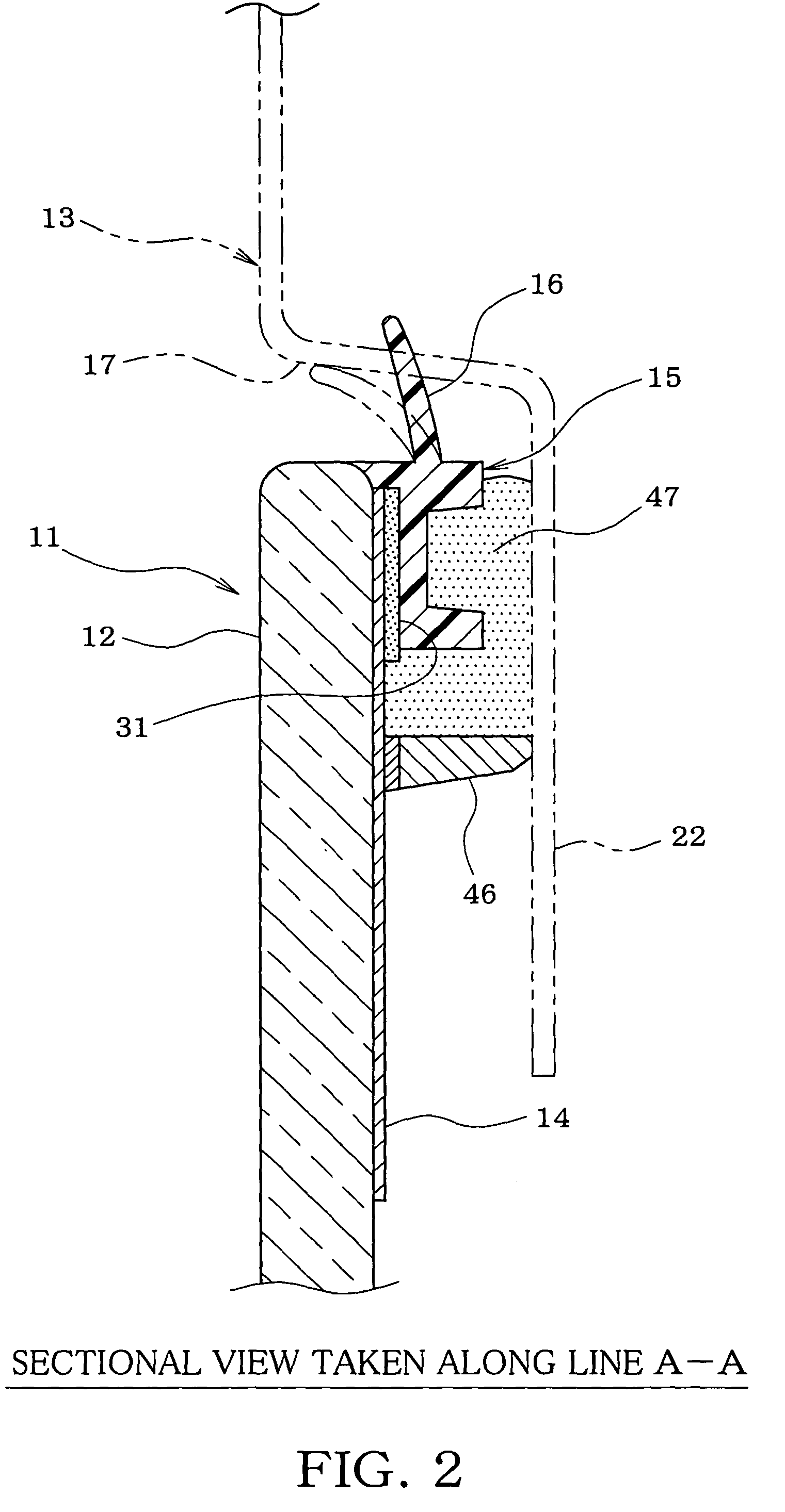
Figure 3
Abstract
Description
TECHNICAL FIELD
[0001] The present invention relates to a method of manufacturing a window assembly attached to a window frame of an automobile or the like and a window pane employed in the manufacture of the window assembly.BACKGROUND ART
[0002] A window assembly attached to a window frame of an automobile is generally provided with a long covering member disposed along a peripheral edge of a window pane for covering a gap between the window pane and the window frame. A paste-like adhesion / sealant is interposed between a back surface of the peripheral edge of the window pane and the window frame and cured so that the window assembly is adhered and fixed to the window frame and sealing is provided between the window assembly and the window frame. It usually takes two days and nights (about 48 hours, for example) to cure the paste-like sealant completely. Accordingly, when the window assembly is to be attached to the window frame, a fixing member provided on a predetermined part of the b...
Examples
embodiment 1
[0034]Embodiment 1 of the invention will be described with reference to FIGS. 1 to 7. Firstly, an outline structure of the window assembly 11 for rear window will be described with reference to FIGS. 1 to 3. The window assembly 11 includes a window pane 12 (rear window glass) formed into a shape (gently curved generally rectangular shape, for example) corresponding to a window frame 13 (see FIG. 2) to which the window pane 12 is to be attached. The window pane 12 has a back surface with an opaque colored layer 14 (also called “frit layer” when the window pane is glass) formed along a peripheral edge of the window pane 12 and having a predetermined width. The opaque colored layer 14 prevents the back surface of the peripheral edge of the window pane 12 from being viewed therethrough at the surface side of window pane 12.
[0035]A long covering member 15 is provided along the peripheral edge of the window pane 12 (peripheral edge of opaque colored layer 14) on the back surface of the wi...
embodiment 2
[0059]Next, embodiment 2 will be described using FIG. 8. In embodiment 2, substantially identical or similar parts are labeled by the same reference symbols as those in embodiment 1 and description of these parts will be simplified. The difference of embodiment 2 from embodiment 1 will be described.
[0060]The covering member 15 and the holding portion 20 are formed while the positioning fixtures 18 is set in the injection mold 35 in embodiment 1. In embodiment 2, however, the covering member 15 and the holding portion 20 are made of the polymer material and thereafter, the positioning fixtures 18 previously made separately are attached to the holding portion 20.
[0061]A space for setting the positioning fixtures 18 is eliminated in the injection mold 48 used in the forming step in embodiment 2, as shown in FIG. 8. In the forming step, only the window pane 12 applied with the adhesive in the same manner as in embodiment 1 is set in the injection mold 48, and the polymer material is the...
embodiment 3
[0064]Next, embodiment 3 will be described using FIGS. 9 and 10. In embodiment 3, substantially identical or similar parts are labeled by the same reference symbols as those in embodiments 1 and 2 and description of these parts will be simplified. The differences of embodiment 3 from embodiments 1 and 2 will be described.
[0065]Only the holding portion 20 holding the positioning fixture 18 is made of the same polymer material as the covering member 15 by the injection molding in the second embodiment. In the third embodiment, however, the entire positioning member 50 for positioning the window pane 12 relative to the window frame 13 is made of the same polymer material as the covering member 15 by the injection molding and adhered to the opaque colored layer 14 of the back surface of the window pane 12 to be fixed, as shown in FIG. 9. The positioning member 50 includes the pedestal 51 formed integrally and coaxially with a protrusion 50a having a tapered face at the distal end side a...