Disk drive cage with shielding member

a technology of shielding cover and drive cage, which is applied in the direction of instrumentation, aperture leaage reduction, casing/cabinet/drawer of electrical apparatus, etc., can solve the problems of inconvenient melting tool use for assembling the shielding cover and the bezel together, and the space in the drive cage is often not fully utilized

Inactive Publication Date: 2010-07-13
HONG FU JIN PRECISION IND (SHENZHEN) CO LTD +1
View PDF11 Cites 17 Cited by
  • Summary
  • Abstract
  • Description
  • Claims
  • Application Information

AI Technical Summary

Benefits of technology

[0004]In a computer or a server, a drive cage is provided to receive disk drives. However, space in the drive cage is often not fully utilized. A void is thus formed that may allow EMI to radiate therefrom. So, a shielding member is needed to cover the void. Generally, the shielding member includes a shielding cover made of steel and a bezel made of plastic attached on the shielding cover. Usually, a bezel is secured to a shielding cover by melting a portion of the bezel with a melting tool and pressing the bezel to the shielding cover. It is inconvenient to use the melting tool to assemble the bezel and the shielding cover together.

Problems solved by technology

However, space in the drive cage is often not fully utilized.
It is inconvenient to use the melting tool to assemble the bezel and the shielding cover together.

Method used


Image

  • Disk drive cage with shielding member
  • Disk drive cage with shielding member
  • Disk drive cage with shielding member

Examples


Embodiment Construction

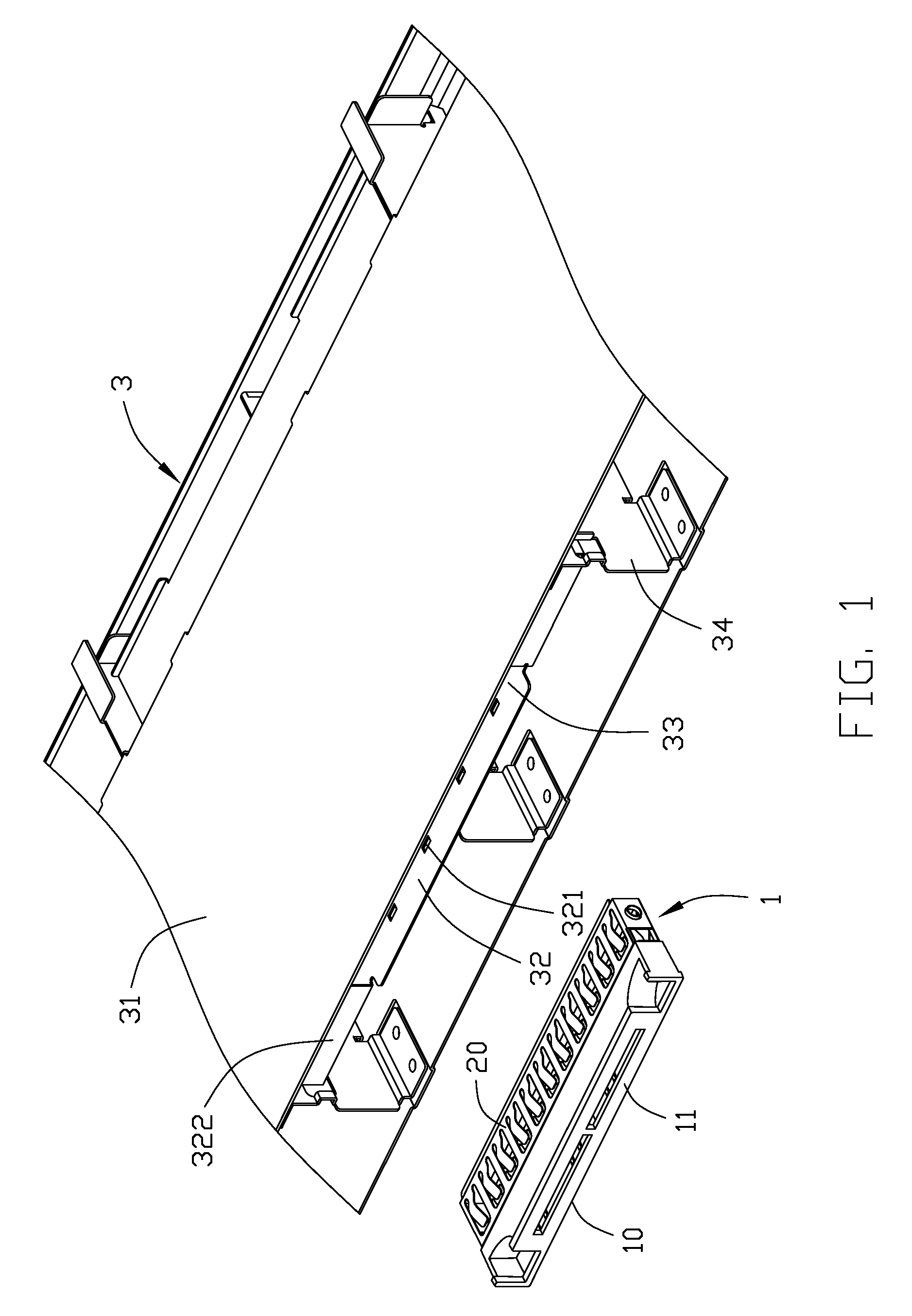
[0013]Referring to FIG. 1, a disk drive cage of a preferred embodiment of the present invention includes a bracket 3 for receiving a plurality of disk drives (not shown) therein, and a shielding member 1 for preventing EMI.

[0014]The bracket 3 includes a top wall 31 and a securing wall 32 parallel to the top wall 31. The securing wall 32 defines a plurality of securing holes 321 therein. A pair of plates 322 extends up from ends of a front edge of the securing wall 32 respectively. Each plate 322 is perpendicular to the securing wall 32 and contacts the top wall 31. A receiving room 33 is enclosed by the pair of plates 322, the top wall 31, and the securing wall 32, for holding the shielding member 1.

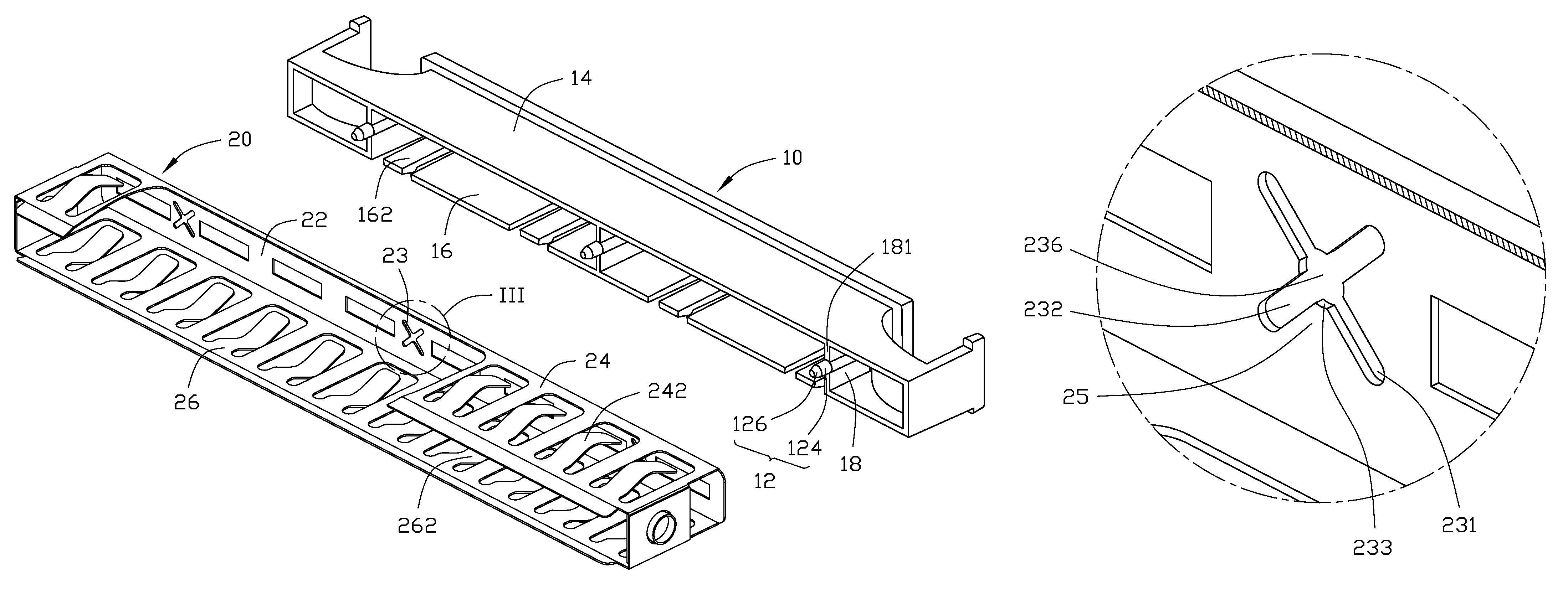
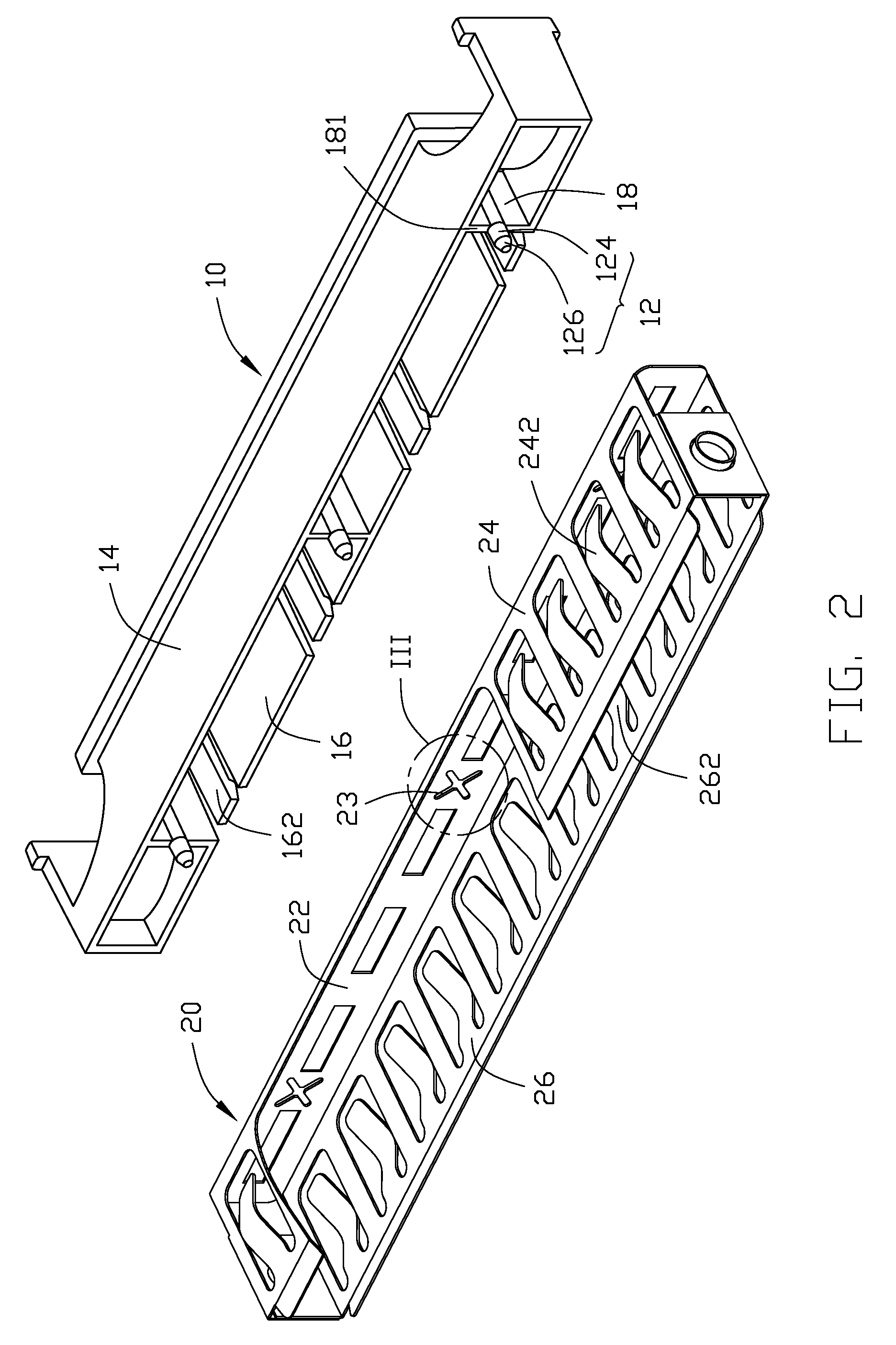
[0015]Referring to FIGS. 1 to 3, the shielding member 1 includes a bezel 10 and a shielding cover 20. The bezel 10 includes a front panel 11, a top panel 14, and a bottom panel 16. A plurality of plates 18 is connected between the top panel 14 and the bottom panel 16. Each plate 18 has a...


PUM


Abstract

A disk drive cage comprises a bracket (3) and a shielding member (1). The bracket comprises a top wall (31) and a securing wall (32) parallel to the top wall. The securing wall defines a plurality of securing holes (321) therein. The shielding member comprises a shielding cover (20) and a bezel (10) attached to the shielding cover. The shielding cover defines a plurality of cross-shaped slots (23). Each cross-shaped slot comprises a first slot (231) and a second slot (232) crossing the first slot. A receiving area (236) is defined in a crossing portion formed by the first and second slots. The bezel comprises a plurality of securing posts (12) interferentially engaging with the plurality of cross-shaped slots, and a plurality of hooks (162) engaging with the securing holes of the securing wall of the bracket. Each securing post comprises a securing portion (124). The securing portion is larger in cross-section than the receiving area. The shielding member is mounted between the top wall and the securing wall.

Description

BACKGROUND[0001]1. Technical Field[0002]The present invention relates to disk drive cages, and more particularly to a disk drive cage with a shielding member for preventing EMI (Electro Magnetic Interference).[0003]2. General Background[0004]In a computer or a server, a drive cage is provided to receive disk drives. However, space in the drive cage is often not fully utilized. A void is thus formed that may allow EMI to radiate therefrom. So, a shielding member is needed to cover the void. Generally, the shielding member includes a shielding cover made of steel and a bezel made of plastic attached on the shielding cover. Usually, a bezel is secured to a shielding cover by melting a portion of the bezel with a melting tool and pressing the bezel to the shielding cover. It is inconvenient to use the melting tool to assemble the bezel and the shielding cover together.[0005]What is needed, therefore, is a disk drive cage having a shielding member, a bezel, and a shielding cover which ca...

Claims


Application Information

Patent Timeline
Patent Type & Authority Patents(United States)
IPC IPC(8): H05K9/00
CPCG06F1/187H05K9/0018G06F1/182
Inventor HE, YU-WEI
Owner HONG FU JIN PRECISION IND (SHENZHEN) CO LTD
Why Eureka
Try Eureka