Conductive coating for reduced reflectivity on electronic displays

a technology of electronic displays and coatings, applied in the field of electronic displays, can solve the problems of reducing the reflectivity of conventional anti-reflective coatings, hampering the viewability of display screens, and reducing the reflectivity of conventional coatings, so as to achieve the effect of controlling the electrical conductivity of the structure and reducing the reflectivity

Active Publication Date: 2010-07-20
L3 TECH INC
View PDF2 Cites 0 Cited by
  • Summary
  • Abstract
  • Description
  • Claims
  • Application Information

AI Technical Summary

Problems solved by technology

Ambient light reflecting off an EMI / RFI shielding coating hampers viewability of the display during daytime.
Anti-reflective coatings are known and can be formed over the shielding (conductive) coating, but a conventional anti-reflective coating does not provide sufficient reflectivity reduction for demanding applications such as cockpit instrument displays.

Method used


Image

  • Conductive coating for reduced reflectivity on electronic displays
  • Conductive coating for reduced reflectivity on electronic displays
  • Conductive coating for reduced reflectivity on electronic displays

Examples


Embodiment Construction

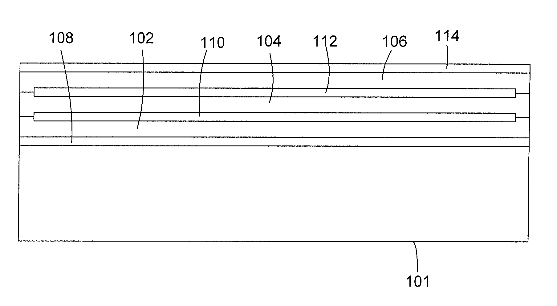
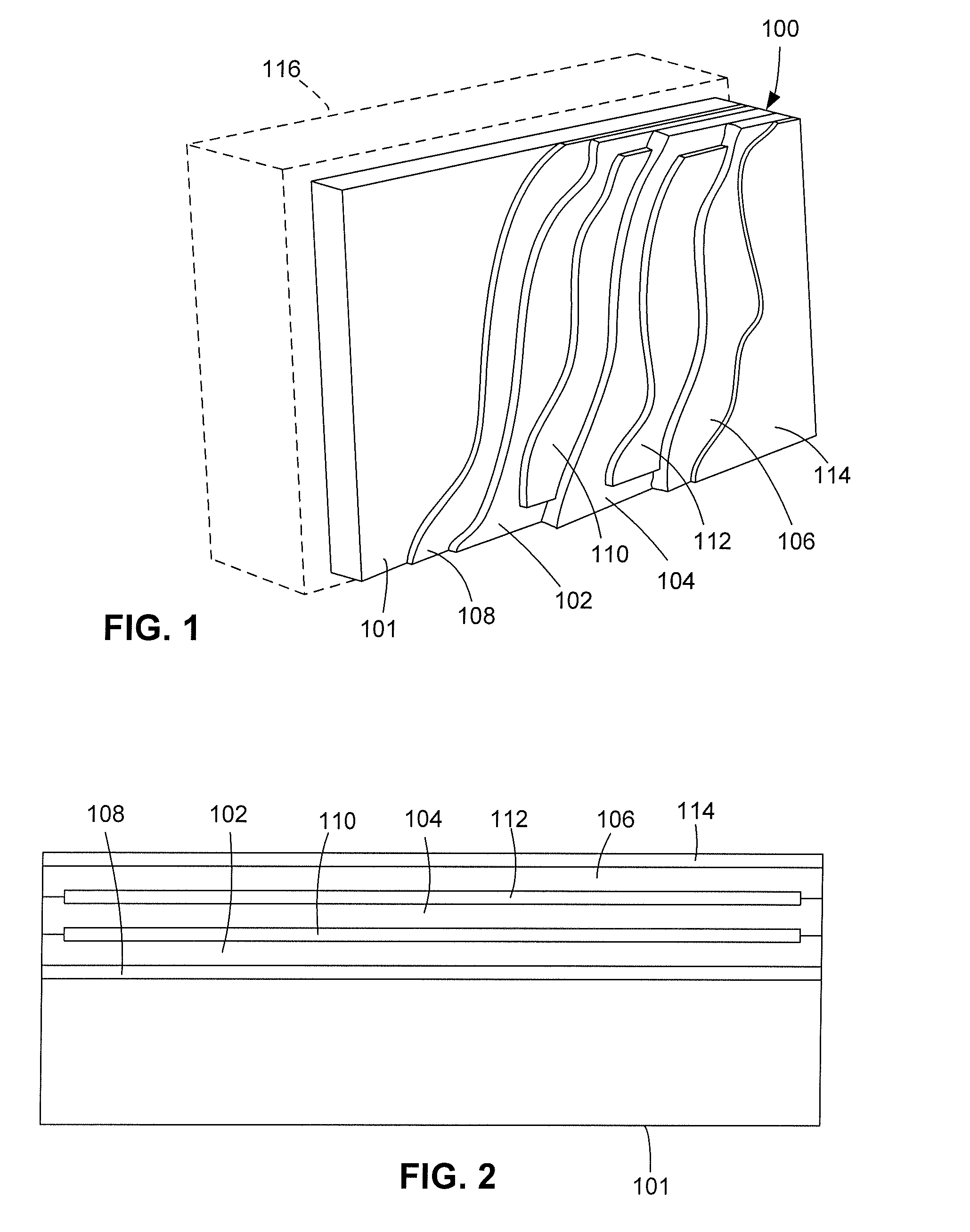
[0013]As illustrated in FIGS. 1-2 (not to scale), in an exemplary embodiment of the present invention a display screen structure 100 comprises a substrate 101 and alternating optical thin-film conductive layers 102, 104 and 106, and optical thin-film dielectric layers 108, 110, 112 and 114. Although in the exemplary embodiment three conductive layers and four dielectric layers are shown for purposes of illustration, in other embodiments there can be more layers or fewer layers of each type, i.e., any suitable number of conductive layers and any suitable number of dielectric layers.

[0014]Display screen structure 100 can be part of an electronic display 116, such as the EMI / RFI-shielded type commonly used with aircraft cockpit instruments. As such, it is desirable for display screen structure 100 to not only provide EMI / RFI shielding but also reflect minimal ambient light so that a viewer can readily see the display during daytime. It may also be desirable for display screen structure...


PUM

PropertyMeasurementUnit
sheet resistanceaaaaaaaaaa
optical structureaaaaaaaaaa

Abstract

In an optical thin-film arrangement on a transparent optical substrate, such as a display screen, two or more conductive layers are stacked in an alternating fashion with one or more dielectric layers. The conductive layer can include, for example, indium-tin oxide (ITO), and the dielectric layer can include an index-matching material. The conductive layers can be in electrical contact with one another at their peripheries to provide EMI / RFI shielding. A structure having more than one conductive layer can be made to have the same net sheet resistance and thus provide the same degree of shielding as a conventional single-layer conductive coating but with lower reflectivity.

Description

BACKGROUND OF THE INVENTION[0001]1. Field of the Invention[0002]The present invention relates generally to electronic displays and, more specifically, to electronic displays with conductive coatings.[0003]2. Description of the Related Art[0004]Many electronic displays have one or more optical coatings or thin films on a glass or similar substrate. Coating the surface of a display screen (e.g., glass) with a conductive material can provide shielding against electromagnetic interference (EMI) and radio frequency interference (RFI), sometimes collectively referred to as EMI / RFI shielding. For example, aircraft cockpit display screens are EMI / RFI shielded to minimize both emitted electromagnetic energy that might interfere with the operation of other instruments and impinging electromagnetic energy that might interfere with the operation of the display instrument itself.[0005]Although a multitude of materials are known in the art for coating transparent optical substrates, the most comm...

Claims


Application Information

Patent Timeline
Patent Type & Authority Patents(United States)
IPC IPC(8): B32B9/00
CPCH05K9/0096
Inventor WALSH, KEVIN
Owner L3 TECH INC
Why Eureka
Try Eureka