
Confocal Displacement Sensor

一种位移传感器、共焦的技术,应用在仪器、科学仪器、光谱测定法/分光光度测定法/单色器等方向,能够解决难以适当地去除背景成分等问题,达到改善测量精度的效果

Active Publication Date: 2022-01-11
KEYENCE
View PDF0 Cites 0 Cited by
  • Summary
  • Abstract
  • Description
  • Claims
  • Application Information

AI Technical Summary

Problems solved by technology

Therefore, it is difficult to properly remove background components

Method used


Image

  • Confocal Displacement Sensor
  • Confocal Displacement Sensor
  • Confocal Displacement Sensor

Examples


Embodiment Construction

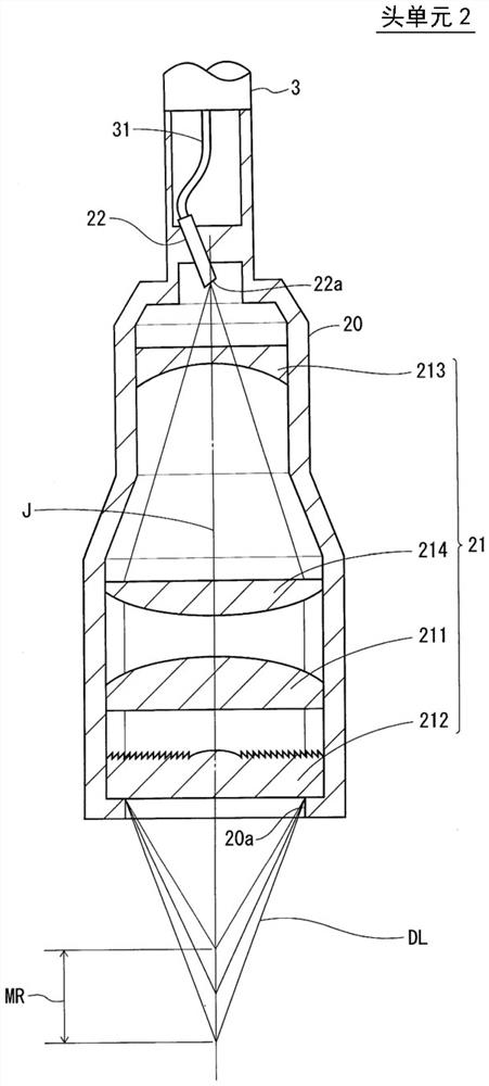
[0032] Embodiments of the present invention will be described below with reference to the drawings. In this specification, for convenience, the direction of the optical axis of the head unit is described as the up-down direction. However, the posture and orientation during use of the head unit are not limited.

[0033] Confocal Displacement Sensor 1

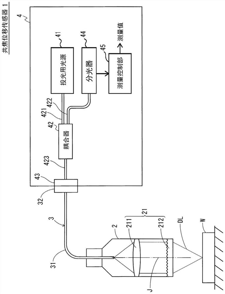
[0034] figure 1 is a system diagram showing a configuration example of the confocal displacement sensor 1 according to the embodiment of the present invention. The confocal displacement sensor 1 is an optical measurement device composed of a head unit 2 , an optical fiber cable 3 and a control unit 4 . This optical measurement device receives reflected light from the measurement object W and measures the displacement of the measurement object W when the detection light DL is emitted from the head unit 2 .

[0035] The head unit 2 and the control unit 4 are connected to each other via an optical fiber cable 3 . The optical fi...


PUM


Abstract

A confocal displacement sensor is provided that has improved measurement accuracy for low reflectivity measurement objects. It includes: a first optical fiber that outputs light from a first output end, and the light for projection is input to its first input end; a second optical fiber that outputs light input through a second input end from a second output end, and the second input The end is opposite to the first output end; the optical component that causes axial chromatic aberration on the detection light emitted through the second output end and converges the detection light to the measurement object; the beam splitter is used to irradiate the measurement object through the optical component Spectrum dispersion of the detection light passing through the second output port by reflection when focusing on the measurement object; measurement control section for calculating the displacement of the measurement object; detachably connecting the second input port to the first output port The optical fiber connection part used; the refractive index matching material between the first output end and the second input end. The second incident end and the first exit end are inclined at a second inclination angle smaller than the first inclination angle of the second exit end.

Description

technical field [0001] The present invention relates to a confocal displacement sensor, and more particularly, to an improvement in a confocal displacement sensor that measures displacement of a measurement object using a confocal optical system. Background technique [0002] The confocal displacement sensor is an optical measurement device that uses the confocal principle (confocal principle) and the phenomenon of axial chromatic aberration (phenomenon of an axial chromatic aberration) to measure the displacement of the measurement object. The light received on the imaging surface of the image of the light source is formed as reflected light by stopping down, and the axial chromatic aberration phenomenon is a phenomenon in which color drift (color drift) in the direction of the optical axis occurs in the image of the light source . [0003] The confocal displacement sensor consists of a pin hole that emits light emitted from a light source for projection as a point light s...

Claims


Application Information

Patent Timeline
Patent Type & Authority Patents(China)
IPC IPC(8): G01B11/02
CPCG01B11/02G01B2210/50G01B11/0608G01B11/026G01J3/0208G01J3/0218G01J3/0291
Inventor 武井英人坂口富一
Owner KEYENCE
Learn More