Method of operating a cargo container scanning crane

a cargo container and scanning technology, applied in special-purpose vessels, hoisting equipment, instruments, etc., can solve the problems of essentially interrupting the established system of port operations, methods to be employed to improve port security may prove severely detrimental to port productivity, and the complexity of processing steps affecting the productivity of ports

Inactive Publication Date: 2010-07-27
PACECO
View PDF17 Cites 28 Cited by
  • Summary
  • Abstract
  • Description
  • Claims
  • Application Information

AI Technical Summary

Benefits of technology

[0023]It is another object of the present invention to provide a cargo container inspection apparatus which is integrated into a buffer operation of the quay crane cycle for transferring a cargo container between ship and shore without slowing the crane transfer cycle.
[0024]It is a further object of the present invention to provide a mobile crane which transfers a cargo container between a buffer station and land transportation with a container inspection procedure integrated into the buffer crane transfer cycle without quay crane container movement interruption.

Problems solved by technology

Thus, the maritime industry provides a delivery system for weapons of mass destruction and every other container could possibly conceal an atomic weapon which, if exploded in a U.S. port, in addition to causing massive destruction, would essentially end international trade.
The methods to be employed to improve U.S. port security may prove severely detrimental to port productivity.
However, these designs have essentially added processing steps to port operations, and the sizes of the machinery and complexity of the processing steps essentially interrupt the established system of port operations.
This factor causes problems when attempting to integrate the technology into dockside cargo container handling.
The problem with instituting high-energy x-ray scanners for cargo container examination, apart from safety concerns, is that the equipment will reduce port productivity by disrupting highly developed port operations and consuming valuable terminal space.
The primary disadvantage is the interruption of the cargo container transfer process between ship and shore.
Most importantly, it interferes with the quay crane off-loading cycle time which is crucial to a ship's berthing time at the dock which must be kept at a minimum.

Method used


Image

  • Method of operating a cargo container scanning crane
  • Method of operating a cargo container scanning crane
  • Method of operating a cargo container scanning crane

Examples


Embodiment Construction

[0032]Reference is made to the drawings for a description of the preferred embodiment of the present invention wherein like reference numbers represent like elements on corresponding views.

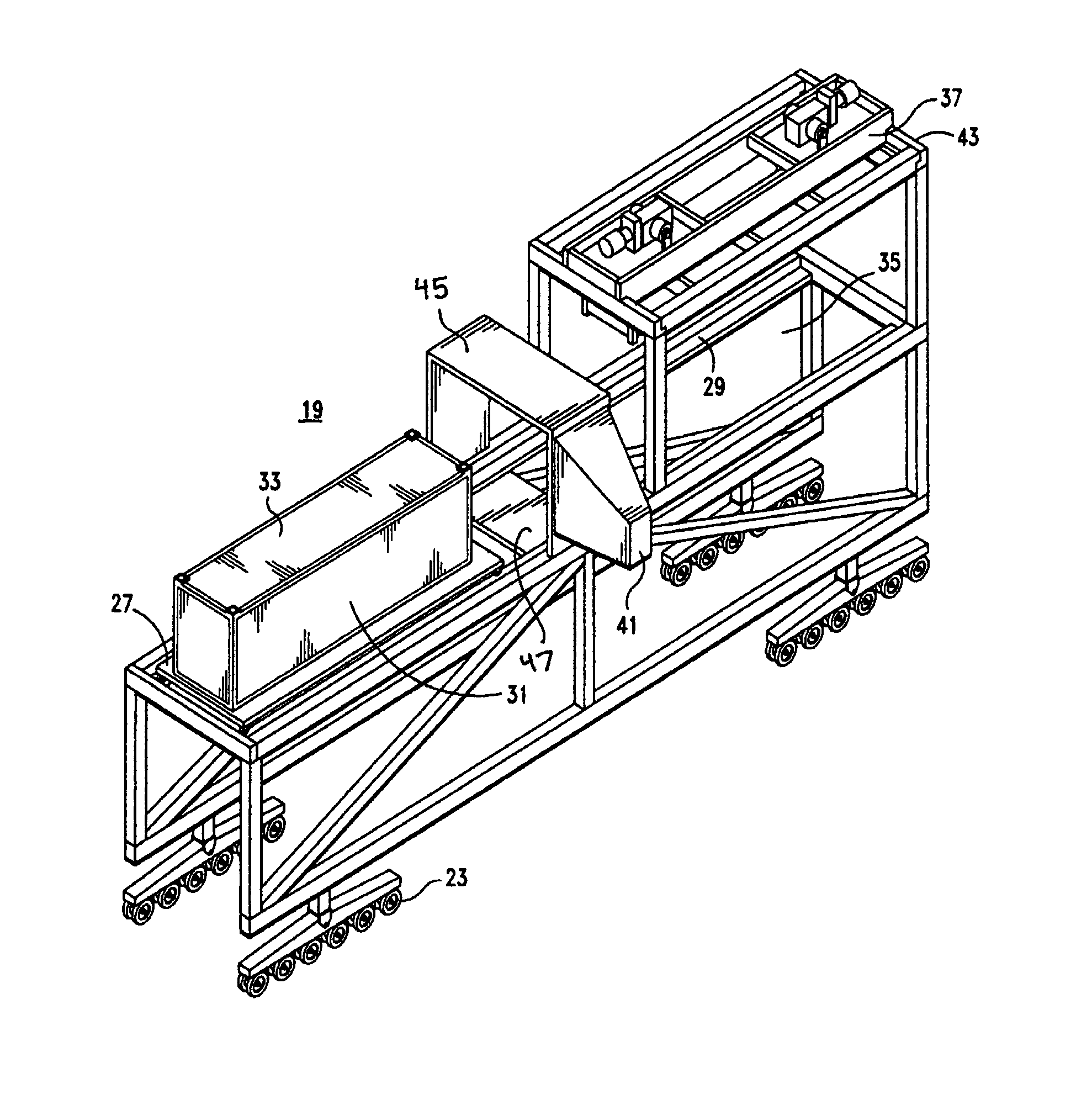
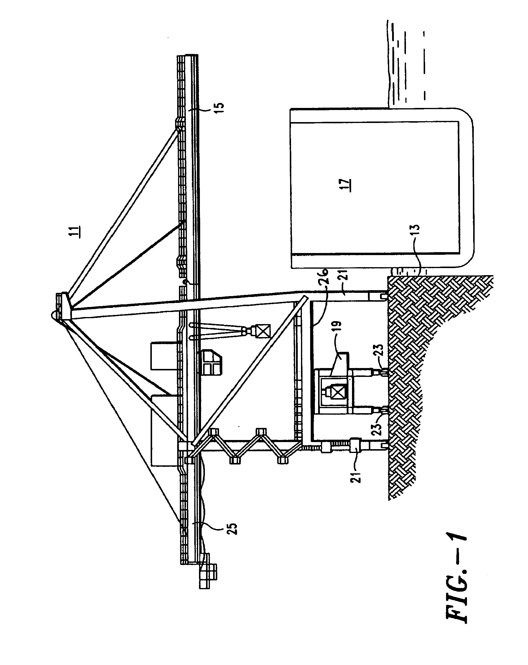
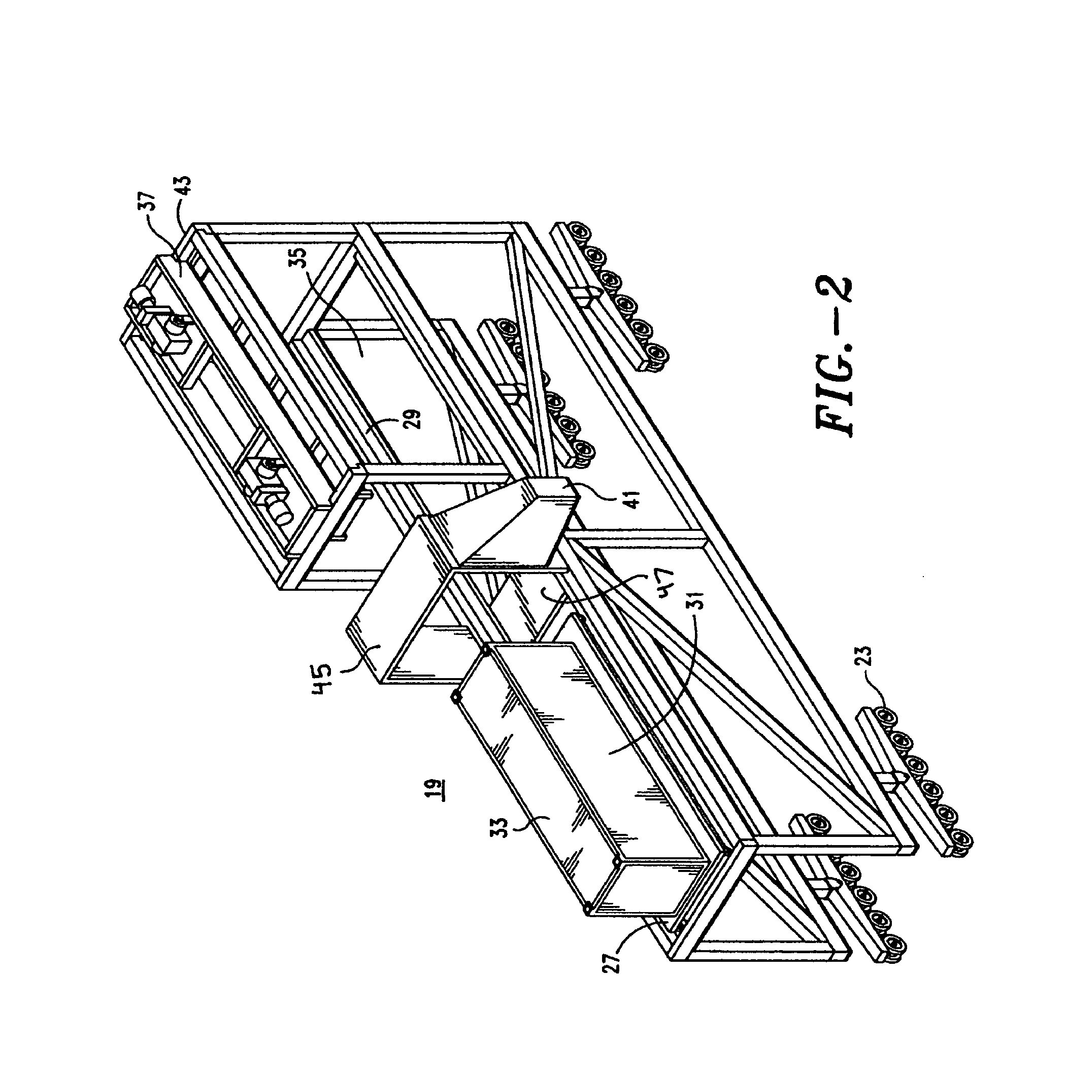
[0033]Reference is made to FIG. 1 of the drawings which shows a typical cargo container handling quay crane 11 located dockside in a shipping port. It is mounted on rails disposed parallel to the dock edge 13. The quay crane traverses the wharf to position itself to project its cantilevered boom 15 over the rows of container cells of the adjacently berthed ship 17 when the boom is lowered. The scanning bridge crane 19 of the present invention is shown disposed below the quay crane between the support legs 21. It is mounted on pneumatic tires 23 for independent movement on the wharf whereby it can be located at variable positions below or adjacent to the quay crane: either between the support legs or alongside under a cantilevered shoreside back reach 25.

[0034]The scanning crane 19 is a low-profile...


PUM

PropertyMeasurementUnit
sizeaaaaaaaaaa
lengthaaaaaaaaaa
massaaaaaaaaaa

Abstract

A mobile cargo container handling buffer crane having a bridge crane mounted thereon for transferring cargo containers between a ship and land transportation with nonintrusive inspection apparatus located at an intermediate transfer position past which a container can be longitudinally translated on a shuttle and thereby non-intrusively inspected.

Description

CROSS REFERENCES TO RELATED APPLICATIONS[0001]The present invention is related to assignees' U.S. patent application Ser. No. 10 / 639,957, filed Aug. 12, 2003, for A Mobile Cargo Container Scanning Crane. It is also related to assignees' U.S. Pat. No. 6,604,904 B2, issued Aug. 12, 2003, for Method for Buffer Crane Operation in Cargo Container Handling. The present invention is further related to the assignees' U.S. Pat. No. 6,602,036 B2, issued Aug. 5, 2003, for Buffer Bridge Crane for Cargo Container Handling Operations. These patent disclosures are incorporated herein by reference.BACKGROUND OF THE INVENTION[0002]1. Field of the Invention[0003]The present invention relates to an apparatus which effects nonintrusive scanning of cargo containers for detection of nuclear based weapons or fissionable material during container transfer between a ship and land transportation.[0004]More particularly, the present invention relates to a buffer crane having nuclear weapon detection scanning ...

Claims


Application Information

Patent Timeline
Patent Type & Authority Patents(United States)
IPC IPC(8): B63B27/00B63B35/00B66C19/00G01N23/04
CPCB65G63/004B66C19/002B65G67/60
Inventor TAKEHARA, TORUICHIMURA, KINYATAM, PHILIP ALEXANDER
Owner PACECO
Why Eureka
Try Eureka