Supercharge Your Innovation With Domain-Expert AI Agents!

Front and rear wheel drive vehicle

a front and rear wheel drive technology, applied in vehicle position/course/altitude control, process and machine control, instruments, etc., can solve problems such as torque slippage or excess torqu

Inactive Publication Date: 2010-08-10
HONDA MOTOR CO LTD
View PDF17 Cites 6 Cited by
  • Summary
  • Abstract
  • Description
  • Claims
  • Application Information

AI Technical Summary

Benefits of technology

[0017]In the front and rear wheel drive vehicle wherein the engine and the motor are controlled independently, when a front wheel pair and a rear wheel pair are driven, a large torque gap may arise if one of the motor driving force command value and the engine driving force command value decreases with respect to the other, leading to a torque slippage or an excess torque. However, in the aforementioned front and rear wheel drive vehicle, it is possible to prevent a shock derived from a torque difference between the engine and the motor, thereby improving a response as a vehicle. This is because the target engine driving force setting means obtains a target driving force of the engine based on driving conditions of the vehicle, a target motor driving force setting means obtains a target driving force of the motor based on driving conditions of the vehicle, and a control means applies a delayed filtering process to the motor only in the case where one of the target engine driving force and the target motor driving force increases and the other one of the target motor driving force and the target engine driving force decreases.

Problems solved by technology

In the front and rear wheel drive vehicle wherein the engine and the motor are controlled independently, when a front wheel pair and a rear wheel pair are driven, a large torque gap may arise if one of the motor driving force command value and the engine driving force command value decreases with respect to the other, leading to a torque slippage or an excess torque.

Method used


Image

  • Front and rear wheel drive vehicle
  • Front and rear wheel drive vehicle
  • Front and rear wheel drive vehicle

Examples


Embodiment Construction

[0032]With reference to FIGS. 1 to 8, one preferred embodiment of the present invention will be described. In this preferred embodiment, a delayed filtering process is applied to a motor in accordance with an increase / decrease in a target engine driving force and a target motor driving force.

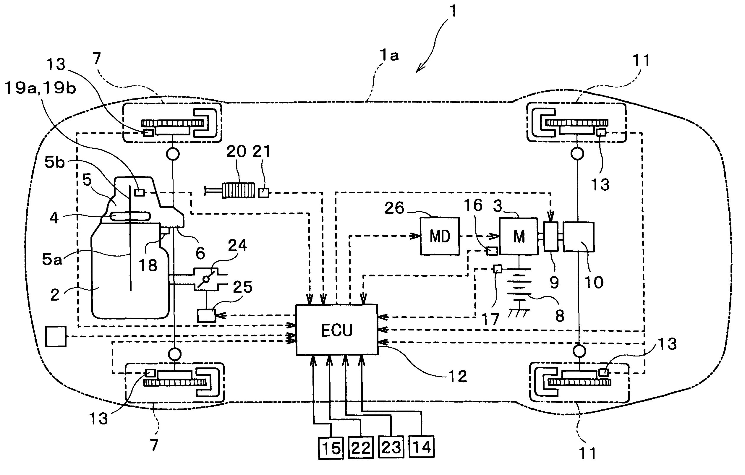
[0033]FIG. 1 shows a hybrid-type four wheel drive vehicle as an example of a front and rear wheel drive vehicle. As shown in the drawing, this hybrid-type four wheel drive vehicle (hereinafter referred to as a vehicle) 1 is equipped with an engine 2 and a motor 3 as power plants for driving.

[0034]The engine 2 is laterally mounted on a front area of the vehicle 1. In addition, the engine 2 is coupled to the front wheels 7, 7 through an automatic power transmission 5 with a torque converter 4 and a front differential 6. Further, the motor 3 is electrically coupled to a battery 8 as a drive source and is mechanically coupled to the rear wheels 11, 11 through a clutch 9 and a rear differential 10.

[0...


PUM


Abstract

A front and rear wheel drive vehicle having a front wheel pair and a rear wheel pair, one of which is driven with an engine and the other one of which is driven with a motor. The vehicle includes an engine driving force setting section which sets a target driving force of the engine based on driving conditions of the vehicle, a motor driving force setting section which sets a target driving force of the motor based on driving conditions of the vehicle and a control section of the motor in accordance with changes of the target engine driving force and the target motor driving force.

Description

CROSS-REFERENCE TO RELATED APPLICATION[0001]This is a Continuation in Part of application Ser. No. 09 / 987,036, filed Nov. 13, 2001 and now abandoned.FIELD OF THE INVENTION[0002]The present invention relates to front and rear wheel drive vehicles wherein a front wheel pair and a rear wheel pair are driven, respectively, and more particularly, to a front and rear wheel drive vehicle wherein one of front and rear wheel pairs is driven with an engine and the other one of the front and rear wheel pairs is driven with a motor.BACKGROUND OF THE INVENTION[0003]Front and rear wheel drive vehicles are generally known, in which both front and rear wheel pairs of the vehicle are driven to improve running through performance of the vehicle. Conventionally, these front and rear wheel drive vehicles are classified into part time four wheel drive type vehicles and full time four wheel drive type vehicles in accordance with the type of driven wheel. In the part time four wheel drive type, the vehicl...

Claims


Application Information

Patent Timeline
Patent Type & Authority Patents(United States)
IPC IPC(8): B60K1/00G06F19/00B60K6/48B60K6/52B60K17/356B60W10/06B60W10/08B60W20/00
CPCB60K6/48B60K6/52B60K17/356B60W10/06B60W10/08B60W20/00B60L2240/423B60L2240/443B60W2510/0657B60W2710/0666B60W2710/083Y02T10/6221Y02T10/6265Y02T10/6286Y02T10/642Y02T10/62Y02T10/64B60W2050/0009B60W2050/001B60W10/12B60W30/18B60W2510/083
Inventor NAKASAKO, TOORUKITANO, KAZUHIKOFUKUDA, TOSHIHIKOYONEKURA, TAKAHIRO
Owner HONDA MOTOR CO LTD
Features
  • R&D
  • Intellectual Property
  • Life Sciences
  • Materials
  • Tech Scout
  • Unparalleled Data Quality
  • Higher Quality Content
  • 60% Fewer Hallucinations
Learn More