Electrical terminal

a technology of electrical connectors and terminals, applied in the direction of coupling device details, coupling device connections, securing/insulating coupling contact members, etc., can solve the problems of fatigue damage, the flexible arm is not protected by other structures, and the electrical connection between the lga terminal and the cpu will be broken

Inactive Publication Date: 2010-08-17
HON HAI PRECISION IND CO LTD
View PDF6 Cites 25 Cited by
  • Summary
  • Abstract
  • Description
  • Claims
  • Application Information

AI Technical Summary

Problems solved by technology

The flexible arm is not protected by other structure and will suffer fatigue damage.
Then the electrical connecting between the LGA terminal and the CPU will be broken when the terminal is damaged.

Method used


Image

  • Electrical terminal
  • Electrical terminal
  • Electrical terminal

Examples


Embodiment Construction

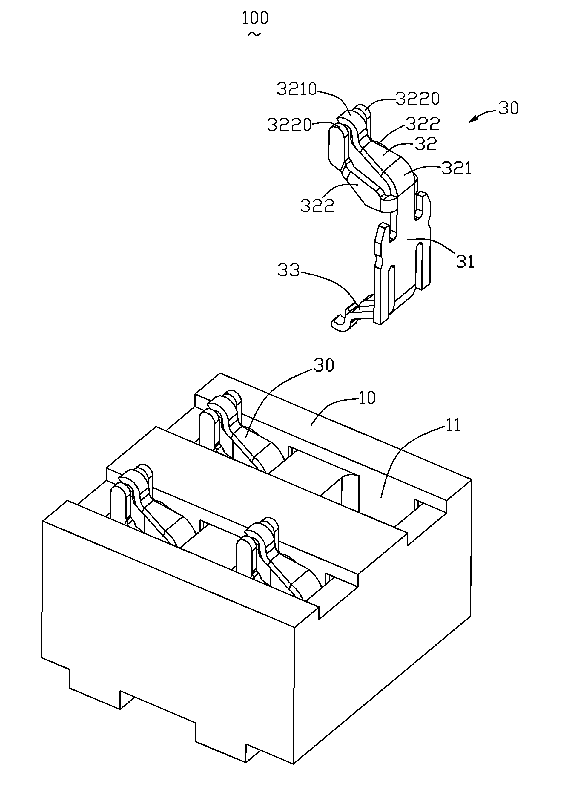
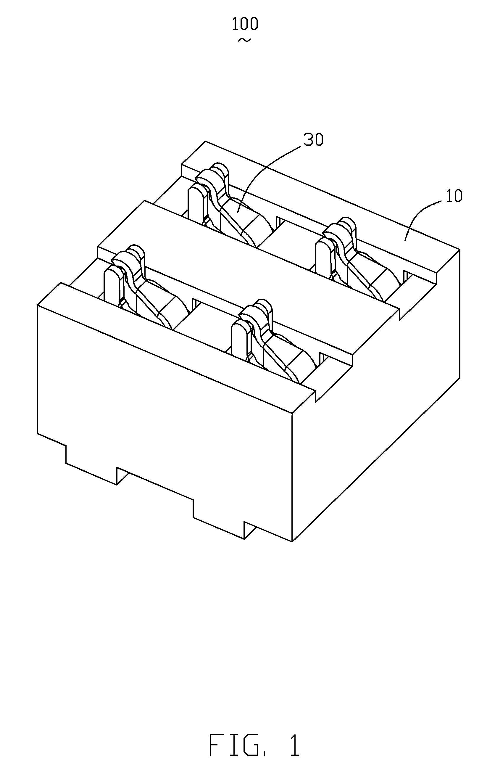
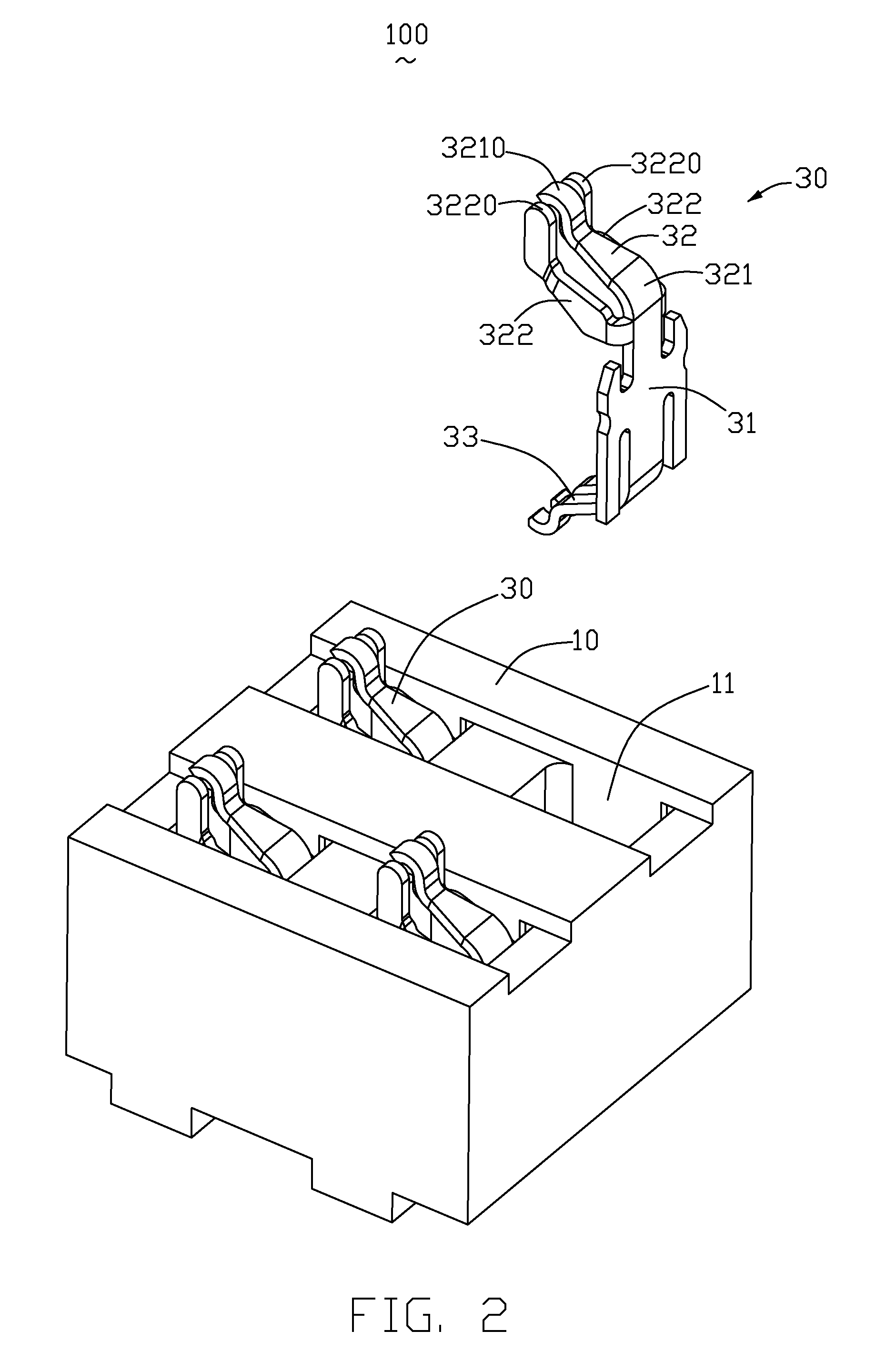
[0013]Referring to FIGS. 1 to 3, an electrical terminal 30 is disposed in a receptacle connector 100. The receptacle connector 100 is disposed on a PCB (print circuit board) (not shown) to receive a CPU (central processing unit) (not shown), and comprises an insulative housing 10 and a plurality of said terminals 30. The PCB defines a plurality of electrical traces, and the terminals 30 are electrically connected to the corresponding electrical traces of the PCB.

[0014]Referring to FIG. 3, the insulative housing 10 is configured of cube. The insulative housing 10 defines a plurality of holes 11, the holes 11 perforate the insulative housing 10 from the upper surface 12 to the lower surface 13. Said terminals 30 are received in the holes 11. We define the holes are along an up-to-down direction.

[0015]Referring to FIGS. 2 to 4, the electrical terminal 30 comprises a main portion 31 and a first and second contacting portion 32, 33. The main portion 31 is fixed in the hole 11, and the fi...


PUM


Abstract

An electrical terminal (30) received in an insulative housing (10), comprising: a main portion (31); a first contacting portion (32); a second contacting portion (33); wherein the first contacting portion comprises at least a flexible arm (321) and at least an inflexible arm (322), the flexible arm can be flexed along an up-to-down direction, and the inflexible arm hard to flex along the up-to-down direction, the flexible and inflexible arms defines a flexible contacting portion (3210) and inflexible contacting portion (3220), respectively. The flexible contacting portion is higher than the inflexible contacting portion along the up-to-down direction, the flexible contacting portion and the inflexible contacting portion are both contacted to a same corresponding electrical contacting portion; the insulative housing defining a plurality of holes, the main portion of the terminal been fixed in the hole, and the first and second contacting portion extending externally from the insulative housing.

Description

BACKGROUND OF THE INVENTION[0001]1. Field of the Invention[0002]The present invention relates to an electrical terminal arranged electrical connector, and more particularly to an electrical terminal arranged in LGA (Land Grid Array) connector.[0003]2. Description of Prior Arts[0004]Usually, the LGA connector disposed on an upper surface of a PCB (print circuit board) is used to receive a CPU (central processing unit), and a plurality of terminals are arranged in the LGA connector. The lower surface of the CPU defines a plurality of electrical pieces, and the upper surface of the PCB forms a plurality of electrical traces. The terminals electrically connect with the electrical pieces and the electrical traces. As the computer developing, the structure of the computer is more and more complex, the accessories of the computer are required more precise and accurate. The U.S. Pat. No. 6,585,527 discloses an LGA terminal, the LGA terminal has a flexible arm, the flexible arm contacts with...

Claims


Application Information

Patent Timeline
Patent Type & Authority Patents(United States)
IPC IPC(8): H01R12/00
CPCH01R12/7082H01R12/714H01R13/2435H01R13/2457H01R13/2492H01R13/41
Inventor LIAO, FANG-JWULIU, JIA-HAU
Owner HON HAI PRECISION IND CO LTD
Why Eureka
Try Eureka