Unlock instant, AI-driven research and patent intelligence for your innovation.

Rear structure of vehicle provided with curtain air bag apparatus

a technology for rear structures and air bags, which is applied in the direction of vehicular safety arrangments, vehicle components, pedestrian/occupant safety arrangements, etc., can solve the problems of difficult to ensure and achieve the effect of smooth expansion and deployment of curtain air bags

Active Publication Date: 2010-08-24
MAZDA MOTOR CORP
View PDF22 Cites 11 Cited by
  • Summary
  • Abstract
  • Description
  • Claims
  • Application Information

AI Technical Summary

Benefits of technology

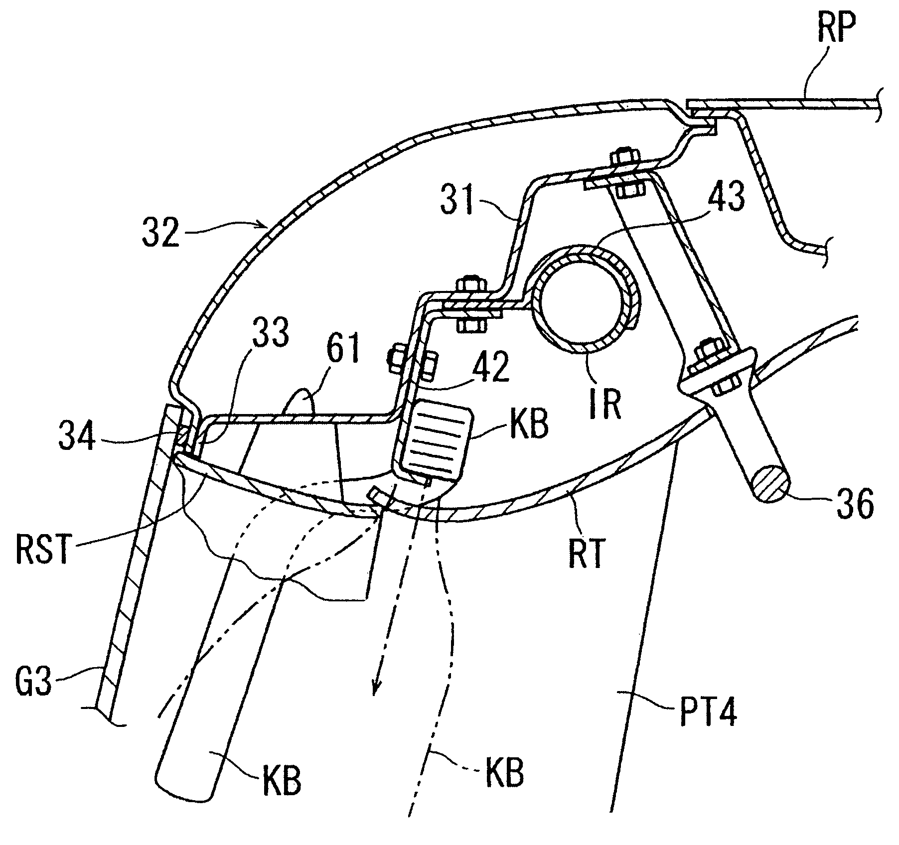
This configuration enables the curtain air bag to be deployed smoothly and effectively within the vehicle cabin while reducing the need for excessive deformation of the rear pillar trim, enhancing its deployability and protection of side window glasses.

Problems solved by technology

However, the rear pillar trim is made of hard material and so is not easily deformed, and thus in a state in which the curtain air bag in a stored state has been positioned significantly inside in the widthwise direction of the vehicle, in order to deploy the curtain air bag inside the vehicle cabin it is necessary to deform the rear pillar trim an extremely large amount, so it is difficult to insure smooth expansion and deployment of the curtain air bag.

Method used


Image

  • Rear structure of vehicle provided with curtain air bag apparatus
  • Rear structure of vehicle provided with curtain air bag apparatus
  • Rear structure of vehicle provided with curtain air bag apparatus

Examples


first embodiment

[0057]First, a first embodiment of the present invention will be described with reference to FIGS. 1 to 13.

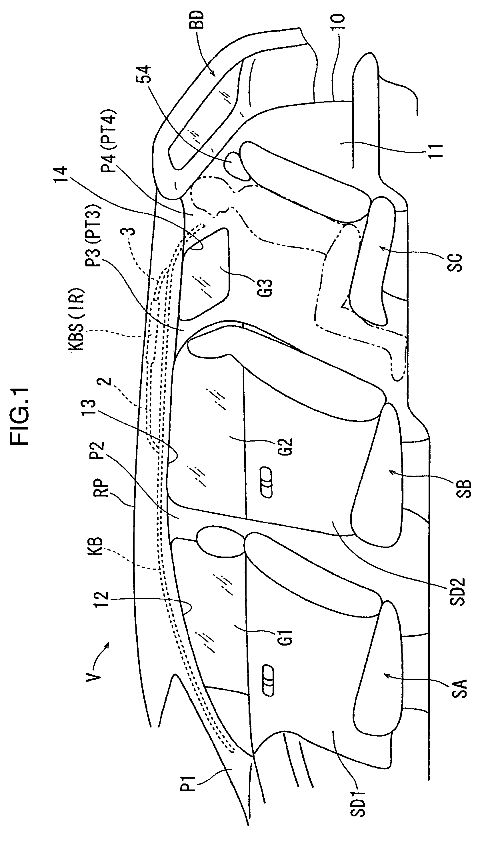
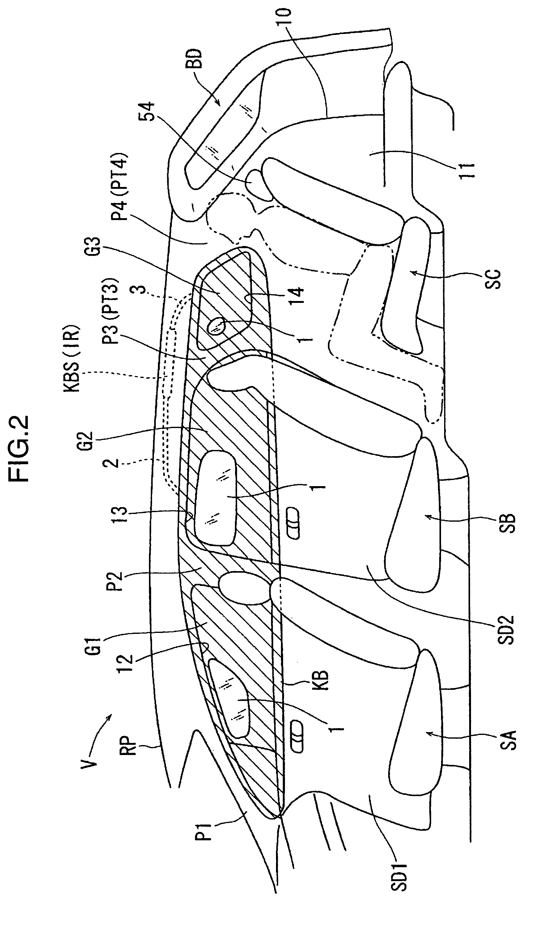
[0058]In FIGS. 1 and 2, a vehicle V includes a front seat SA, a second row seat SB disposed to the rear of the front seat SA, and a third row seat SC that is a specific seat disposed to the rear of the second row seat SB. A side door for the front seat SA is indicated by numeral SD1, and a side door for the second row seat SB is indicated by numeral SD2. The vehicle V includes, as pillars, in order from front to rear, an A pillar P1, a B pillar P2, a C pillar P3 as a middle pillar, and a D pillar P4 as a rear pillar. The area between left and right D pillars P4 is used for a rear opening 10 that is opened or closed by a back door BD, and through the rear opening 10, personal belongings are placed in or removed from a cargo compartment 11 to the rear of the third row seat SC.

[0059]The side door SD1 opens or closes a passenger opening 12 between the A pillar P1 and the B pillar P...

second embodiment

[0095]Next is a description of a second embodiment of the present invention with reference to FIGS. 25 to 27. The basic configuration of the second embodiment is the same as that of the first embodiment (see FIGS. 1 to 12), so the same constituent elements as in the first embodiment are given the same numerals and a duplicate description thereof is omitted here (also true for the third and fourth embodiments described below). Also, in the second embodiment as well, although a description with symbols is omitted in the drawings, same as in the first embodiment, the separation distance of the curtain air bag KB in a stored state from the side window glass G3 in the widthwise direction of the vehicle, in the portion along the rear edge of the side window glass G3, is set so as to be smaller than, among the portion along the upper edge of the side window glass G3, the portion in the vicinity of the middle pillar trim PT3 (see FIG. 13; L24). This is also true for the third and fourth emb...

third embodiment

[0116]Next is a description of a third embodiment of the present invention with reference to FIGS. 33 to 37.

[0117]In the third embodiment, as shown in FIGS. 33 to 37, the outside end edge of the roof trim RT in the widthwise direction of the vehicle, between the pillar trim PT3 and the rear pillar trim PT4, protrudes slightly in the widthwise direction of the vehicle, but does not reach the side window glass G3. In the immediate vicinity of the side window glass G3, the roof side trim RST is provided extending in the front-rear direction along the upper edge of the side window glass G3. That is, the roof side trim RST is positioned to the outside of the roof trim RT in the widthwise direction of the vehicle. The roof side trim RST is set up in a case in which, when moving the roof trim RT from outside the vehicle to inside the vehicle cabin through a vehicle opening and installing the roof trim RT to the roof, the roof trim RT cannot be largely formed for a reason such as the openin...


PUM


Abstract

A middle pillar trim and a rear pillar trim positioned to the front and rear of a side window glass are each harder than a roof trim. A curtain air bag fixed to a rear pillar is deployed in a vehicle cabin while a predetermined end edge of the front of the rear pillar trim in the widthwise direction of a vehicle is deformed toward the front. The separation distance of the curtain air bag in a stored state from the side window glass in the widthwise direction of the vehicle is L1 (L2) in the portion of the curtain air bag along the rear edge of the side window glass, and L4 in the portion of the curtain air bag at the upper edge of the side window glass near the middle pillar trim, and the separation distance L1(L2) is smaller than the separation distance L4.

Description

BACKGROUND OF THE INVENTION[0001]1. Field of the Invention[0002]The present invention relates to a rear structure of a vehicle provided with a curtain air bag apparatus.[0003]2. Background Art[0004]In vehicles, and particularly in automobiles, an air bag apparatus is ordinarily provided in order to protect a passenger when, for example, the vehicle rolls or is involved in a collision. One type of air bag is a so-called curtain air bag, which expands and deploys inside the vehicle cabin so as to cover a side window glass. One type of curtain air bag is long in the front-rear direction so as to cover a plurality of units of side window glass disposed at intervals in the front-rear direction. According to the disclosure of Japan Patent Publication Ser. No. 2004-189099A, a curtain air bag is formed extremely long in the front-rear direction, such that it is possible to cover all of three units of window glass disposed at intervals in the front-rear direction. In the configuration disclo...

Claims


Application Information

Patent Timeline
Patent Type & Authority Patents(United States)
IPC IPC(8): B60R21/213B60R21/232
CPCB60R21/213B60R21/232B60R2013/0287
Inventor YAMAGIWA, TSUYOSHIHIDAKA, SHOUICHIROUNAKAO, HIROAKIHIRATA, MOTOHARUWATANABE, TSUTOMUSAIKI, HIDEHARUUMEKI, TETSUYA
Owner MAZDA MOTOR CORP