Output power port management control

a technology for controlling the output power port, which is applied in the direction of constant-current supply dc circuits, constant-current supply ac circuits, ac network voltage adjustment, etc., and can solve the problems of increasing the amount of bulky items a user is required to carry

Inactive Publication Date: 2010-08-24
IGO INC
View PDF26 Cites 13 Cited by
  • Summary
  • Abstract
  • Description
  • Claims
  • Application Information

AI Technical Summary

Problems solved by technology

This complete shutdown is inconvenient to a user trying to utilize or power both devices.
This often means that users have to carry multiple converters: one for an AC input power source, and another for a DC input power source.
This often means that users are typically required to carry multiple power converters to power multiple devices.
Thus, by carrying multiple mobile devices, users are often forced to carry more than one power supply converter, thereby increasing the amount of bulk a user is required to carry.

Method used


Image

  • Output power port management control
  • Output power port management control
  • Output power port management control

Examples


Embodiment Construction

[0015]The numerous innovative teachings of the present invention will be described with particular reference to the presently exemplary embodiments. However, it should be understood that this class of embodiments provides only a few examples of the many advantageous uses and innovative teachings of the inventor. In general, statements made in the specification of the present application do not necessarily delimit any of the various claimed inventions. Moreover, some statements may apply to some inventive features, but not to others.

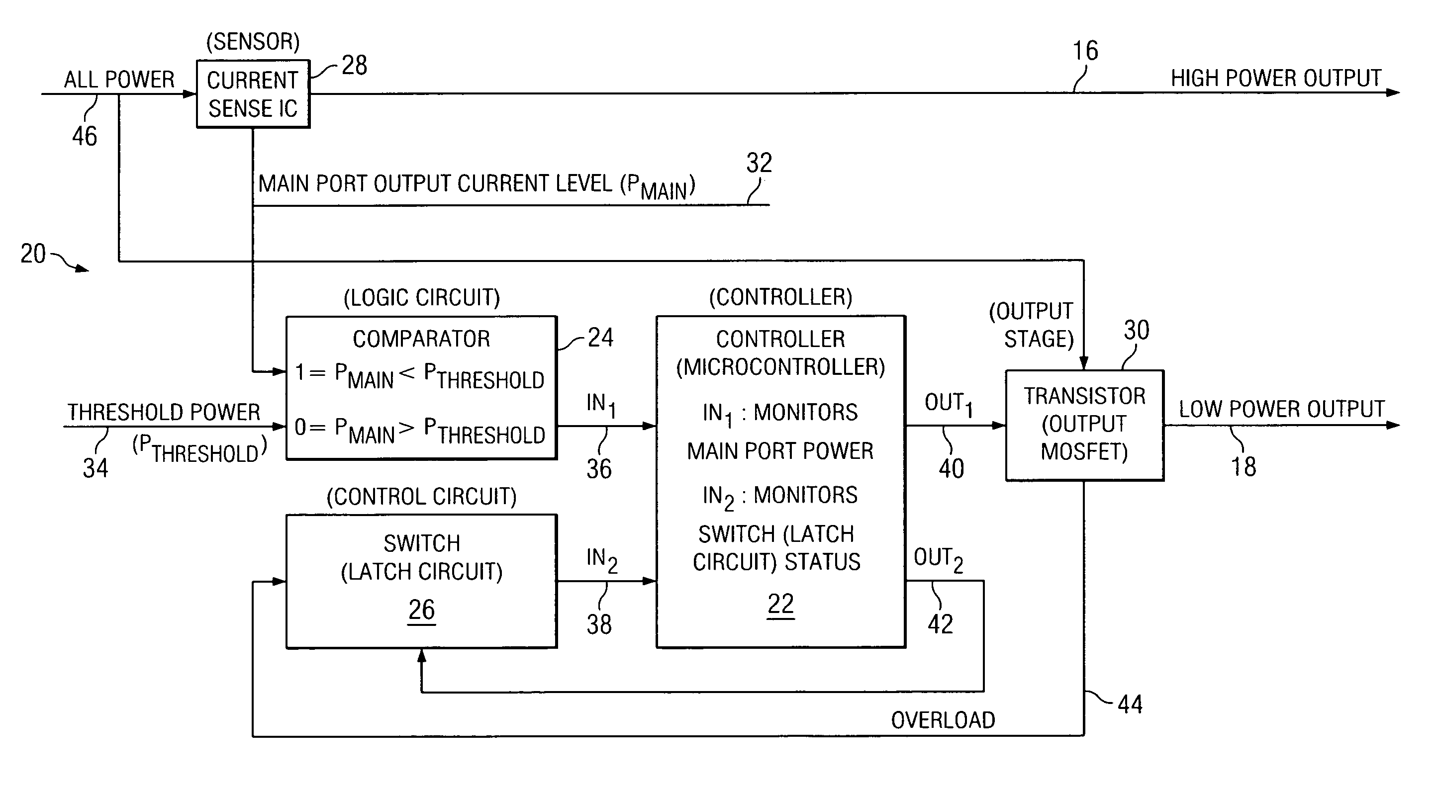
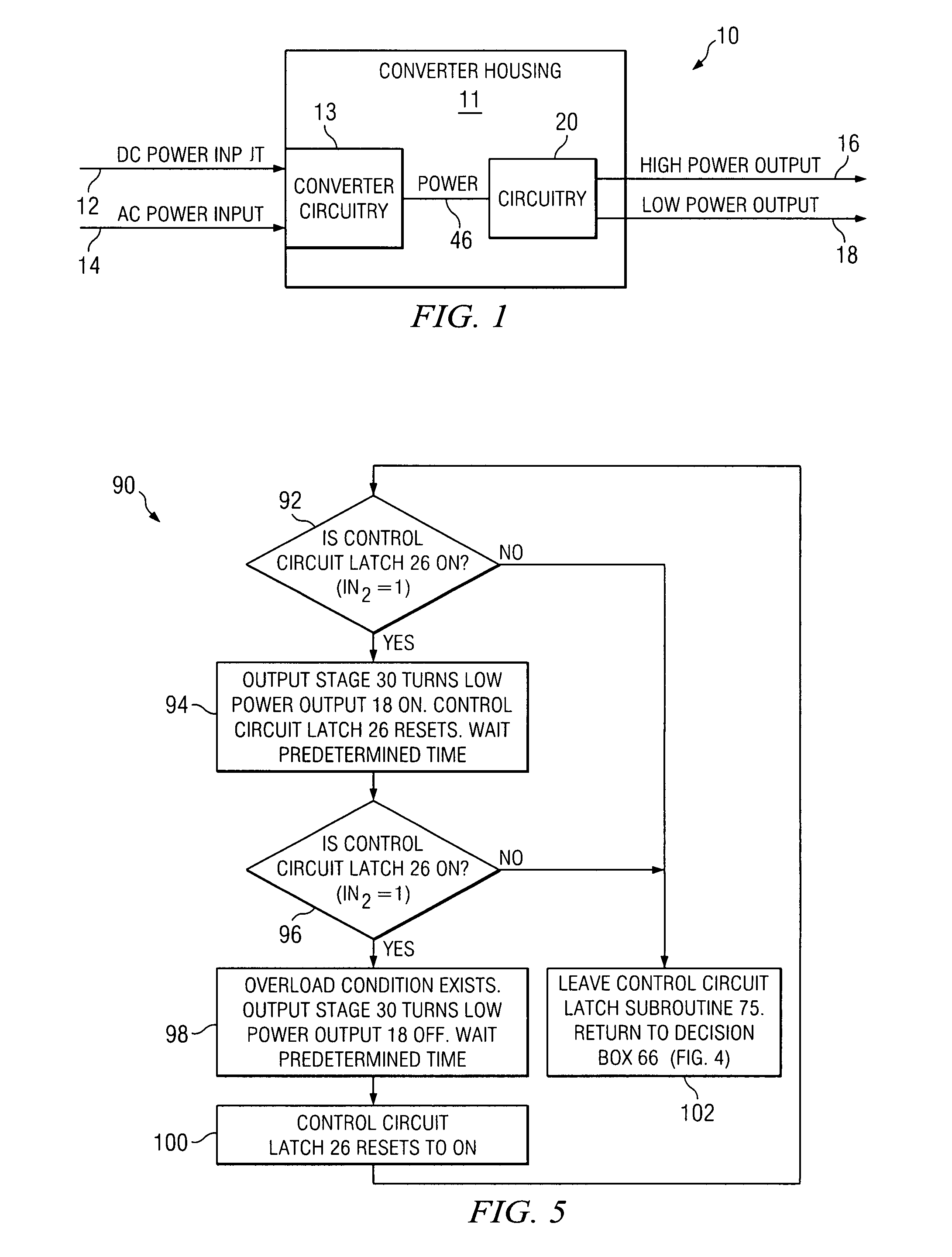
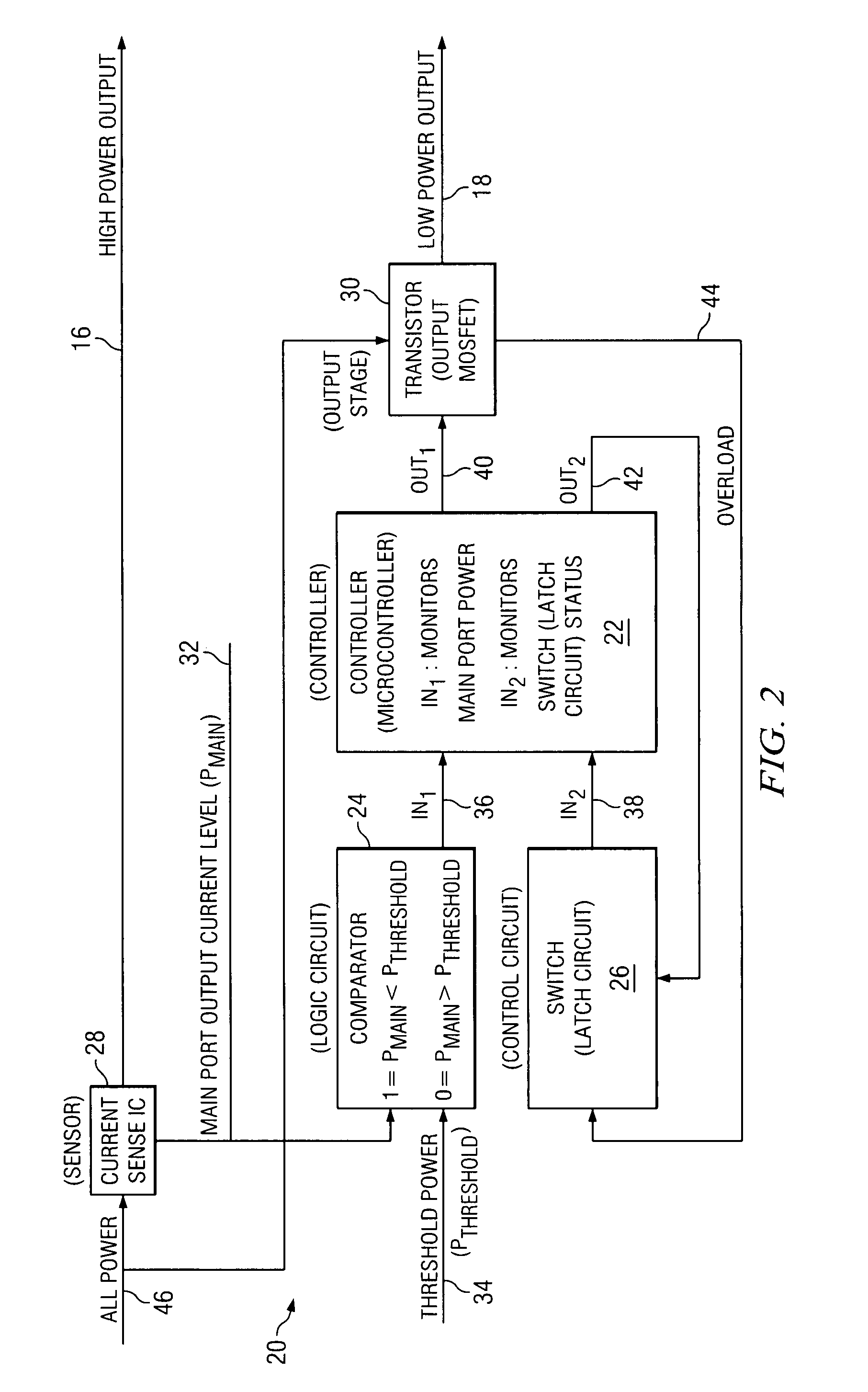
[0016]There is shown in FIG. 1 a block diagram of dual input AC / DC power converter 10 having dual DC voltage outputs in accordance with the present invention. The converter may be a dual input AC / DC converter as shown, but may also be a single input AC or DC input converter as desired. Dual input AC / DC power converter 10 comprises input converter power circuitry 13 and power converter circuitry 20. Power converter circuitry 20 is seen housed in converter ...


PUM


Abstract

A power converter that gives priority to the high power output and only provides power to the low power output when the total potential output power is equal to or less than the rated power of the power converter. A specific power threshold is established, and when the high power output remains below this threshold for a period of time the low power output is allowed to turn on. If the high power output subsequently exceeds this threshold for a period of time, then an electronic circuit powers down the low power output in order to keep the total output power below the rated power of the power converter. Subsequently, the high power output is checked against the threshold to determine if the low power output can be turned on again. If the high power output is below the threshold, then the low power output is turned on.

Description

FIELD OF THE INVENTION[0001]The present invention generally relates to the field of power converters, and more particularly to a power converter having both a high power output and low power output for use with portable electronic devices.BACKGROUND OF THE INVENTION[0002]As the use of mobile electronic devices, such as PC notebooks, PDAs, cellular telephones, MP3 players, cameras and the like continues to increase, the need for low cost, compact power converters to power and recharge these devices also continues to increase. Most manufacturers of mobile devices typically include plug-in power adapters along with these mobile devices to power and charge batteries of these devices.[0003]Today's power converters are typically AC-to-DC, or DC-to-DC power converters, which are configured to either step-up or step-down the DC voltage input delivered to the mobile device. With AC-to-DC converters, for example, users can power most mobile devices by simply plugging the converter into a stan...

Claims


Application Information

Patent Timeline
Patent Type & Authority Patents(United States)
IPC IPC(8): H02H3/06H02H3/20H02H3/00H02H3/08
CPCH02J1/14H02M1/32H02M3/156H02M2001/009H02M1/009
Inventor DUBOSE, GARRYBRIGGS, ANN
Owner IGO INC
Why Eureka
Try Eureka