

Light emitting device having a package formed with fibrous fillers
a technology of fibrous fillers and light emitting devices, which is applied in the direction of discharge tubes/lamp details, discharge tubes luminescnet screens, electric discharge lamps, etc., can solve problems such as defectiveness, and achieve the effects of good condition, high commercial value, and increased area contacting the reflecting film
- Summary
- Abstract
- Description
- Claims
- Application Information
AI Technical Summary
Benefits of technology
Problems solved by technology
Method used
Image

Examples
Embodiment Construction
[0040]Now, the description will be made for the embodiments of the present invention with reference to the drawings attached hereto.
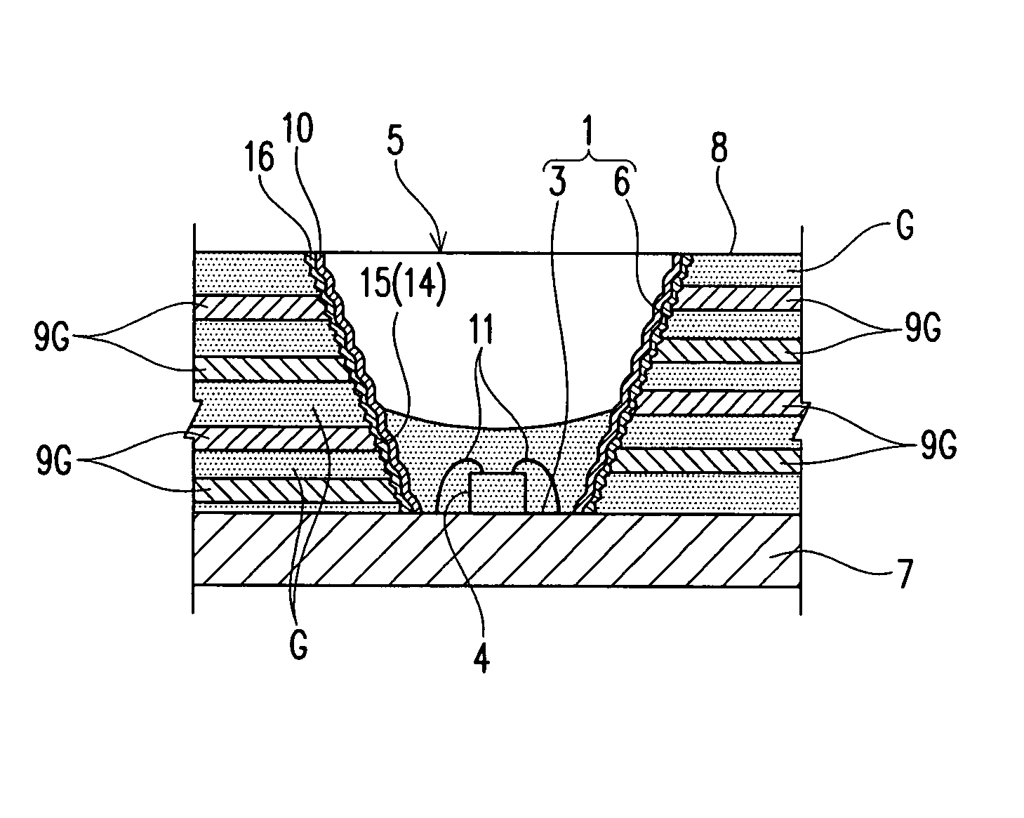
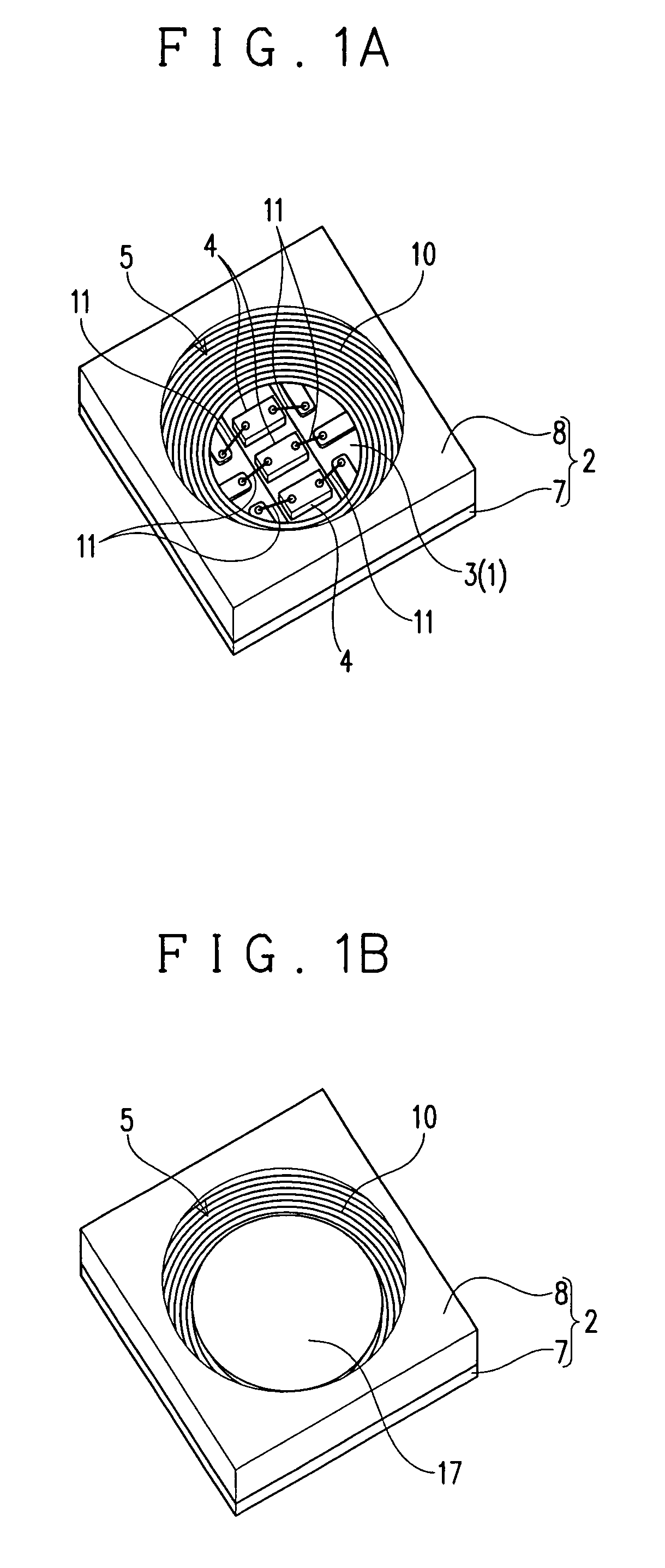
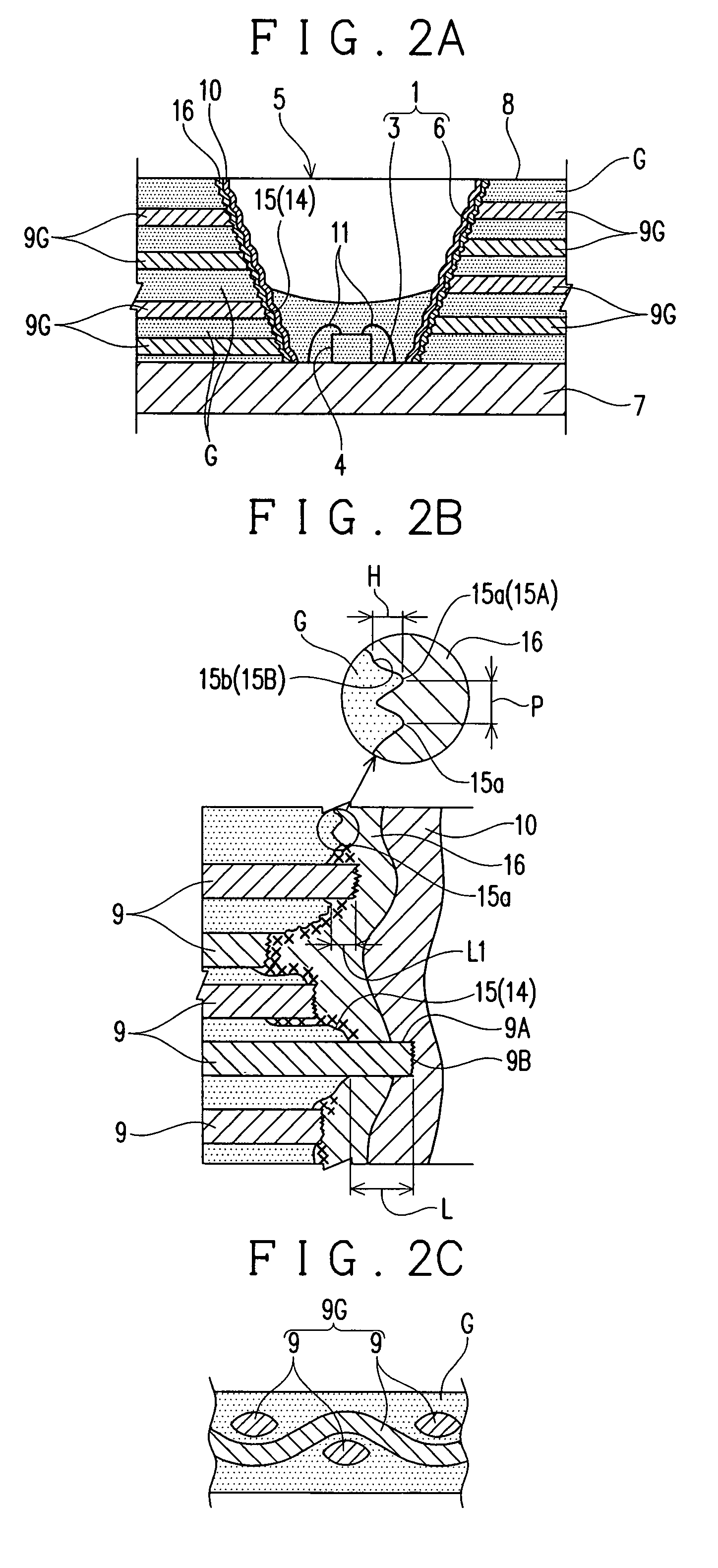
[0041]FIGS. 1A and 1B illustrate a light emitting diode as an example of a light emitting device. This light emitting diode includes a package 2 having a recessed portion 1 and three light emitting elements 4 mounted on a bottom surface 3 of the recessed portion 1. FIG. 1A illustrates the light emitting diode in a state just before it is filled with a light transmitting resin material, such as silicone resin or epoxy resin for sealing the three light emitting elements 4, and FIG. 1B illustrates the light emitting diode filled with a light transmitting material 17. Herein, illustration is made for the light emitting diode with three light emitting elements 4 disposed within the recessed portion, but it is possible to dispose one or two, or four or more light emitting elements 4 within the recessed portion. The light emitting elements 4 each have a positi...
PUM
 Abstract
Description
Claims
Application Information