Circular impact mill unit and cycle impact mill method using impact mill

A technology of impact mill and impact mill, which is applied in the direction of grain processing, etc., can solve the problems that the finished products cannot be divided into different particle sizes, the impact mill is easy to enter foreign matter, and the impact mill is prone to damage, etc., and achieves good results. Promote application value, compact structure, and small footprint

Inactive Publication Date: 2017-09-08
王毅
View PDF6 Cites 1 Cited by
  • Summary
  • Abstract
  • Description
  • Claims
  • Application Information

AI Technical Summary

Problems solved by technology

However, the impact mill has the following defects: 1. The impact mill is easy to enter foreign matter, causing damage inside the machine and causing damage
2. The existing impact mill can only crush but cannot control the particle size of the crushed finished product
In different industries (such as grain processing industry), sometimes finished products with different particle sizes are required, and the existing impact mill equipment cannot divide the finished products into different particle sizes and send them out
3. When the particle size of the material particles is greater than the maximum value that the impact mill can process, the impact mill is prone to damage

Method used


Image

  • Circular impact mill unit and cycle impact mill method using impact mill
  • Circular impact mill unit and cycle impact mill method using impact mill

Examples


Embodiment Construction

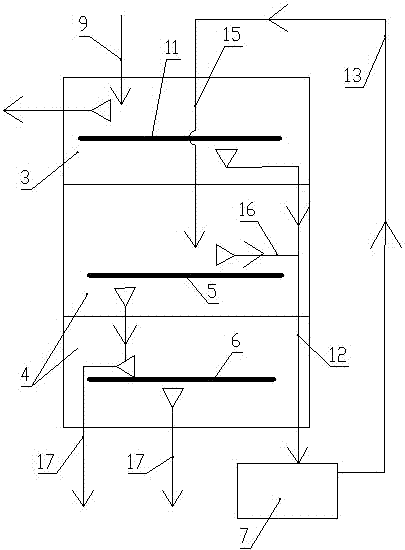
[0039] figure 2 The direction indicated by the middle arrow is the flow direction of the material. figure 2 The "△" with the tip pointing down in the middle indicates the undersize, and the "△" symbol with the tip pointing to the left or right indicates the oversize.

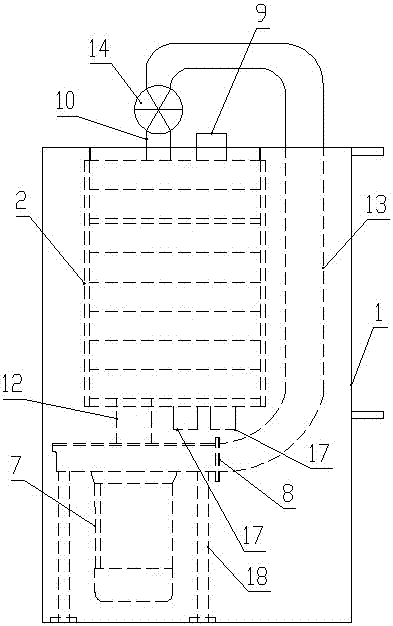
[0040] Such as figure 1 and figure 2 As shown, the circulating impact mill unit of the present invention includes a casing 1, a sieve 2 is installed in the casing 1, a cleaning bin 3 and a sieving bin 4 arranged below the cleaning bin 3 are arranged in the sieve 2; A circulating screen 5 and a grading screen mechanism located below the circulating sieve 5 are arranged inside, and the grading screen mechanism includes several grading screens 6;

[0041] The casing 1 directly below the sieve 2 is provided with an impact mill 7, and the discharge port 8 of the impact mill 7 is located on the top of the impact mill 7; The feed port 10; the feed port 9 of the sieve body communicates with the cleaning bin 3.

...


PUM


Abstract

The invention discloses a circulating impact pulverizing unit and method. The unit includes a casing, a screen is installed in the casing, a cleaning bin and a screening bin are arranged in the screen, and a circulating screen and a grading screen are arranged in the screening bin. There is an impact mill in the casing, and the top of the sieve is provided with a sieve body feed port and a circulating feed port; the cleaning bin is provided with a cleaning screen for separating impurities; the discharge port of the impact mill is connected to the mill. The discharge pipe of the pulverizer, the discharge pipe of the pulverizer extends upward and is connected with a discharger after being bent; the circulating feeding port is connected with a screening feeding channel, and a circulating discharging channel is arranged above the circulating screen, and the circulating The discharging channel is communicated with the feeding channel of the pulverizer; the grading screen mechanism is connected with a number of sieve discharge pipes at each grading screen. The invention occupies less area, has low cost and low energy consumption, can avoid the damage of large foreign objects, can process cyclically and continuously discharge materials, avoid that the pulverized materials fail to meet the particle size requirements, and divide the processed materials into different particle sizes. Finished product sent.

Description

technical field [0001] The invention relates to a kind of impact crushing equipment for crushing materials, which can be used in various industries such as feed, mine, food and medicine. Background technique [0002] Crushing materials is a necessary process in many processing industries, and pulverizers are widely used in industries. Existing crushing equipment includes impact mills, hammer mills, etc. [0003] Existing hammer mills include housings, rotors with hammers, screens and motors. The material enters the machine body, the hammer rotor rotates at a high speed driven by the motor, and the crushed material meets the requirements and passes through the screen to become a finished product. The disadvantage of this kind of mill is that the discharge is not smooth, and the phenomenon of material accumulation often occurs. The part of the crushed material remaining in the mill is repeatedly crushed by the hammer, which wastes energy. In addition, due to the problem of ...

Claims


Application Information

Patent Timeline
Patent Type & Authority Patents(China)
IPC IPC(8): B02C13/13B02C13/26B02C13/284B02C13/286B02C23/12
Inventor 王毅王洪福
Owner 王毅
Why Eureka
Try Eureka