Device for driving an oil pump in a transmission

a technology for transmissions and oil pumps, applied in the direction of machines/engines, liquid fuel engines, gears, etc., can solve the problems of affecting the performance of the transmission, the the noise of the transmission, etc., and achieves the effect of less noise generation, less play, and better gear meshing

Active Publication Date: 2010-11-23
ZF FRIEDRICHSHAFEN AG
View PDF18 Cites 6 Cited by
  • Summary
  • Abstract
  • Description
  • Claims
  • Application Information

AI Technical Summary

Benefits of technology

[0005]The invention provides that the gear shaft has a mounting on both sides of the gear wheel, which meshes with another gear wheel. This is advantageous because the bending deflection of the gear shaft is smaller, which results in better gear meshing; a drive connection with less play, and less generated noise.
[0006]The first bearing of the gear shaft, preferably a roller bearing, is supported in the transmission housing, while the second gear shaft bearing is arranged in the pump housing which has a corresponding bearing bore to receive the bearing. The pump housing itself is preferably cylindrical and is fitted into a corresponding bore in the transmission housing so that the forces resulting from the second bearing are transferred indirectly to the transmission housing. This gives the advantage of a stable, rigid and bend-resistant mounting by which the gear shaft is centered and a saving of axial structural space. A further contribution to the latter is that in the area of the pump housing, the gear shaft is hollow to accommodate within itself a part of the pump drive shaft, in particular the drive connection between the gear shaft and the pump shaft.
[0007]The drive connection between the gear shaft and the pump shaft can be formed with positive locking or by friction force locking: preferably, a carrier ring with a carrier profile is pressed into the end of the hollow shaft and engages with the pump shaft with positive locking. Thanks to the mounting of the front end of the gear shaft according to the invention, the drive connection between the gear shaft and the pump shaft can be made within a fine tolerance, i.e., it can be made with very little radial play. The advantages of this are quiet running and longer life.

Problems solved by technology

For optimum meshing of the gear stage such overhang mounting is unsuitable, inasmuch as bending deflection and tilting at the gear meshing point can have negative results in relation to gear noise and lifetime.
Moreover, it is also a disadvantage that because of the bending of the spur gear shaft (cross shaft) relatively large play is needed in the drive connection between the spur gear shaft and the pump drive shaft, which results in a corresponding increase in noise and a more rapid wear.

Method used


Image

  • Device for driving an oil pump in a transmission
  • Device for driving an oil pump in a transmission

Examples


Embodiment Construction

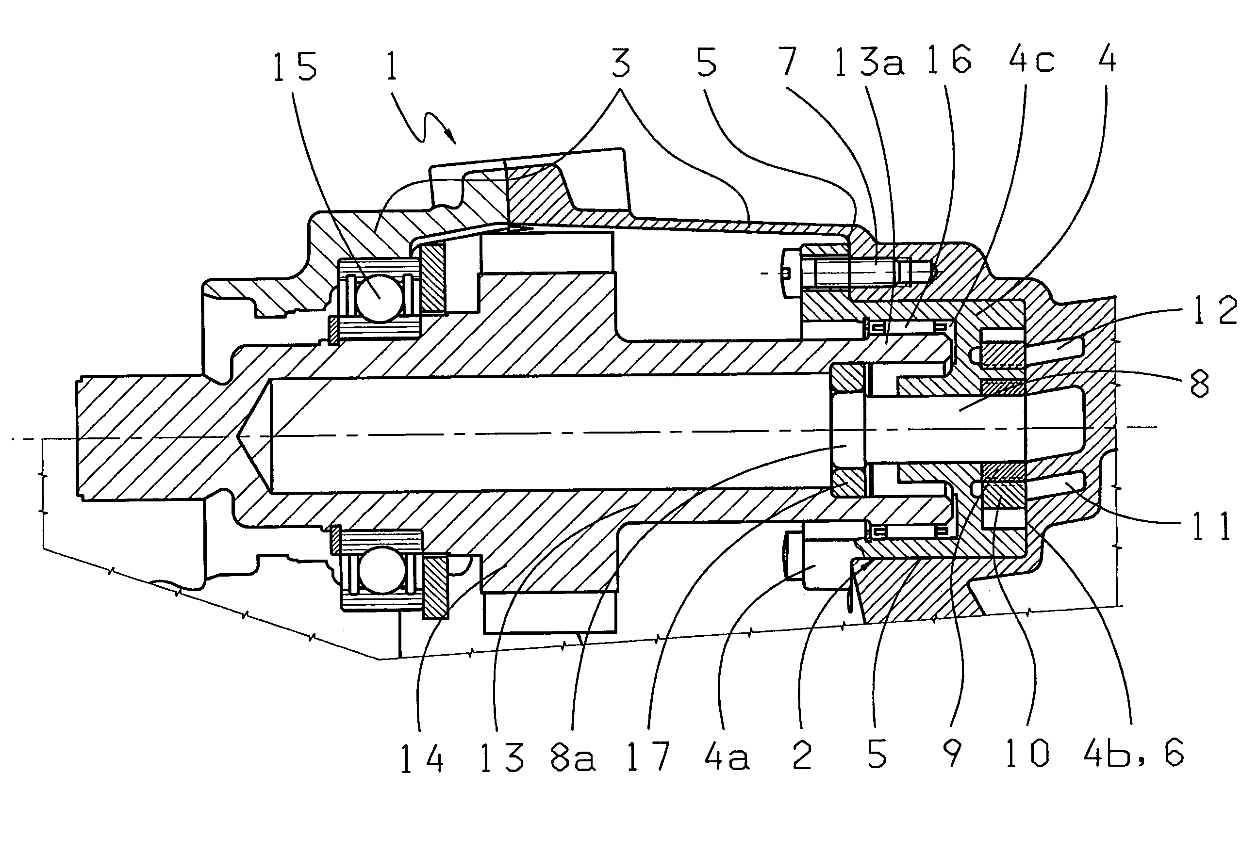
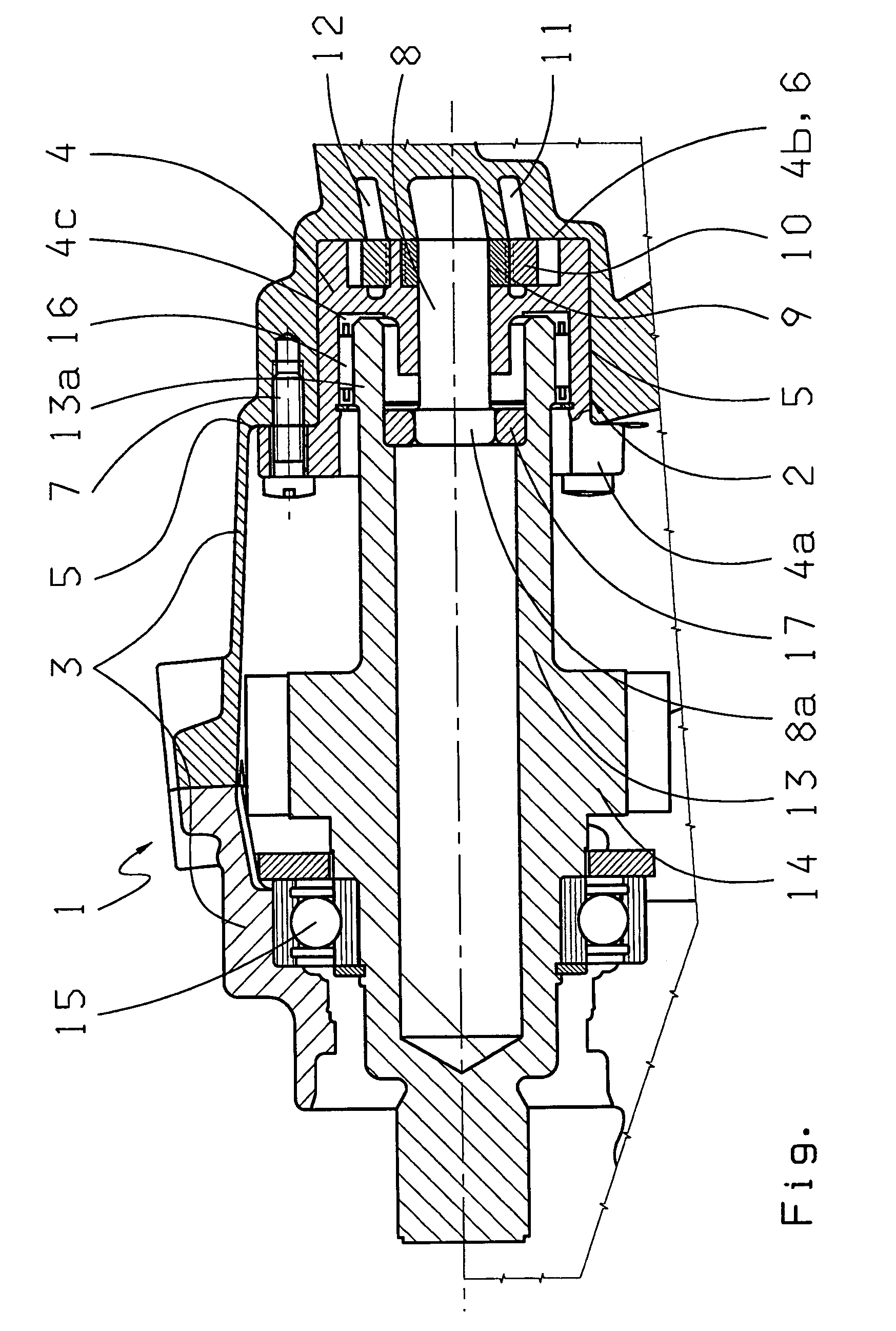
[0013]FIG. 1 shows a sectioned view of a device 1 for driving an oil pump 2 which is arranged in a transmission housing 3 of a motor vehicle (not shown). The oil pump 2 has a pump housing 4 of cylindrical outer shape which is fitted into a cylindrical bore 5 in the transmission housing 3. The pump housing 4 has a flange 4a and an end face 4b, which is in contact with a corresponding flat surface 6 on the transmission housing 3. The pump housing 4 is fixed firmly against the transmission housing 3 by way of fixing bolts 7 in such a manner that the end face 4b is supported against the flat surface 6 of the transmission housing—leaving for this a corresponding gap S between the flange 4a and the transmission housing 3. The pump housing 4 holds a pump shaft 8 that drives an inner rotor 9 which meshes with an outer rotor 10, for example in the manner of an internally geared or a crescent moon pump. A suction chamber 11 and a pressure chamber 12 are arranged in the transmission housing 3....


PUM


Abstract

A device (1) for driving an oil pump (2) for a transmission of a motor vehicle, having a pump housing (4), a transmission housing (3), a pump shaft (8), and a gear shaft (13), which is in rotationally fixed connection with the pump shaft (8). The gear shaft has a gear wheel (14) and is mounted in the transmission housing as part of a gear stage. It is proposed that the gear shaft (13) is bearing-mounted on both sides of the gear wheel.

Description

[0001]This application claims priority from German Application Serial No. DE 10 2006 026 631.5 filed Jun. 8, 2006.FIELD OF THE INVENTION[0002]The invention concerns a device for driving an oil pump for a transmission of a motor vehicle.BACKGROUND OF THE INVENTION[0003]Motor vehicle transmissions, especially automatic transmissions, need at least one oil pump to deliver and build up the pressure of oil (ATF) in an oil circuit for the lubrication of gears and bearings, for the actuation of shift elements and / or for cooling the transmission. As main or primary pumps for the supply of oil to an automatic transmission, engine-driven, gear-type pumps or radial piston pumps are known. From DE 102 27 314 A1 by the Applicant, a so-termed converter neck pump is known, which is made as an internally geared pump (crescent moon pump) and is driven by the converter neck of the torque converter. In addition to such main pumps, secondary pumps are also used for automatic transmissions, and perform ...

Claims


Application Information

Patent Timeline
Patent Type & Authority Patents(United States)
IPC IPC(8): F04C2/10F04C15/00F16H47/08F16H57/04
CPCF16H57/0434Y10T74/2186
Inventor BARTHEL, LOTHARKARSTENS, TOBIAS
Owner ZF FRIEDRICHSHAFEN AG
Why Eureka
Try Eureka