Balancing arm with friction hinge

a technology of friction hinges and balancing arms, which is applied in the direction of construction, stands/trestles, building aids, etc., can solve the problems of wear and play, assembly, and collapse of the loaded friction hinge, and achieve the effects of less complex, less expensive, and less difficult to assembl

Active Publication Date: 2022-09-06
VLAAR INNOVATIONS
View PDF6 Cites 1 Cited by
  • Summary
  • Abstract
  • Description
  • Claims
  • Application Information

AI Technical Summary

Benefits of technology

[0009]The invention aims to alleviate the disadvantages of the prior art. In particular, the invention aims to provide for a friction hinge that is less complex, less expensive, less difficult to assemble and / or provides less play. Thereto, the invention provides for a balancing arm, comprising a folding arm that extends between a first end that is held in position, and a second end on which a load is carried, a first folding arm portion that extends from the first end of the folding arm being pivotably connected via a friction hinge to a second folding arm portion that extends to the second end of the folding arm, further comprising a balancing force device that is arranged to act between the first and second ends of the folding arm across the friction hinge to balance the load carried on the second end of the folding arm, wherein the friction hinge is embodied as a friction hinge with adjustable friction, characterized in that the friction hinge includes a head and a socket arranged to pivot relative to each other when the folding arm portions pivot, and a screw clamp connection extending across the friction hinge to cause the head and the socket to be engaged, the head comprising a tapered contact surface that cooperates with a correspondingly shaped tapered contact surface of the socket in a self-releasing clamp connection, the contact surfaces simultaneously each forming both a bearing surface and a friction surface for the friction hinge.
[0015]When at least one of the contact surfaces is integrally formed with a folding arm portion, manufacturing and assembly may be further facilitated. For example, the contact surface of the head may be integral with one folding arm portion, and the contact surface of the socket may be integral with the other folding arm portion. The socket may e.g. be integrally formed in a die-cast folding arm portion, and the head may be integrally formed in a pressed steel sheet folding arm portion.
[0016]When the friction hinge comprises a set of interspaced heads facing each other, and matching sockets in interspace between, the self-centering capacity of the friction hinge may be increased further. The heads may e.g. be carried on facing sides of a yoke on a first folding arm portion, and the sockets may be carried on opposing sides of a boom end of a second folding arm portion that is held in the yoke, and a bolt may be provided that crosses the yoke and the boom end.
[0017]By arranging the male and female contact surfaces to be in direct contact, the part count may be reduced further. As an alternative, e.g. to prevent seizure, the male and female contact surfaces may be in indirect contact via a shim that is interposed between the contact surfaces.
[0018]When the head, socket or shim is made of plastics material, friction and wear may be controlled more easily, and a conformity of the cooperating surfaces may be achieved by deformation of the material without the need for precise manufacturing.

Problems solved by technology

A difficulty with an adjustable friction hinge in a balancing arm, is that the pivoting of the ends of the folding arm about the friction hinge while under load of the balancing force device causes issues of wear and play, and requires specific measures to prevent that pivoting may loosen the screw clamp connection used to set the amount of friction and may cause collapse of the loaded friction hinge.
Assembly, while under load of the balancing force device, is another difficulty.
A disadvantage of the known adjustable friction hinge is that it is relatively complex and costly to manufacture, and still has issues with assembly and play.

Method used


Image

  • Balancing arm with friction hinge
  • Balancing arm with friction hinge
  • Balancing arm with friction hinge

Examples


Embodiment Construction

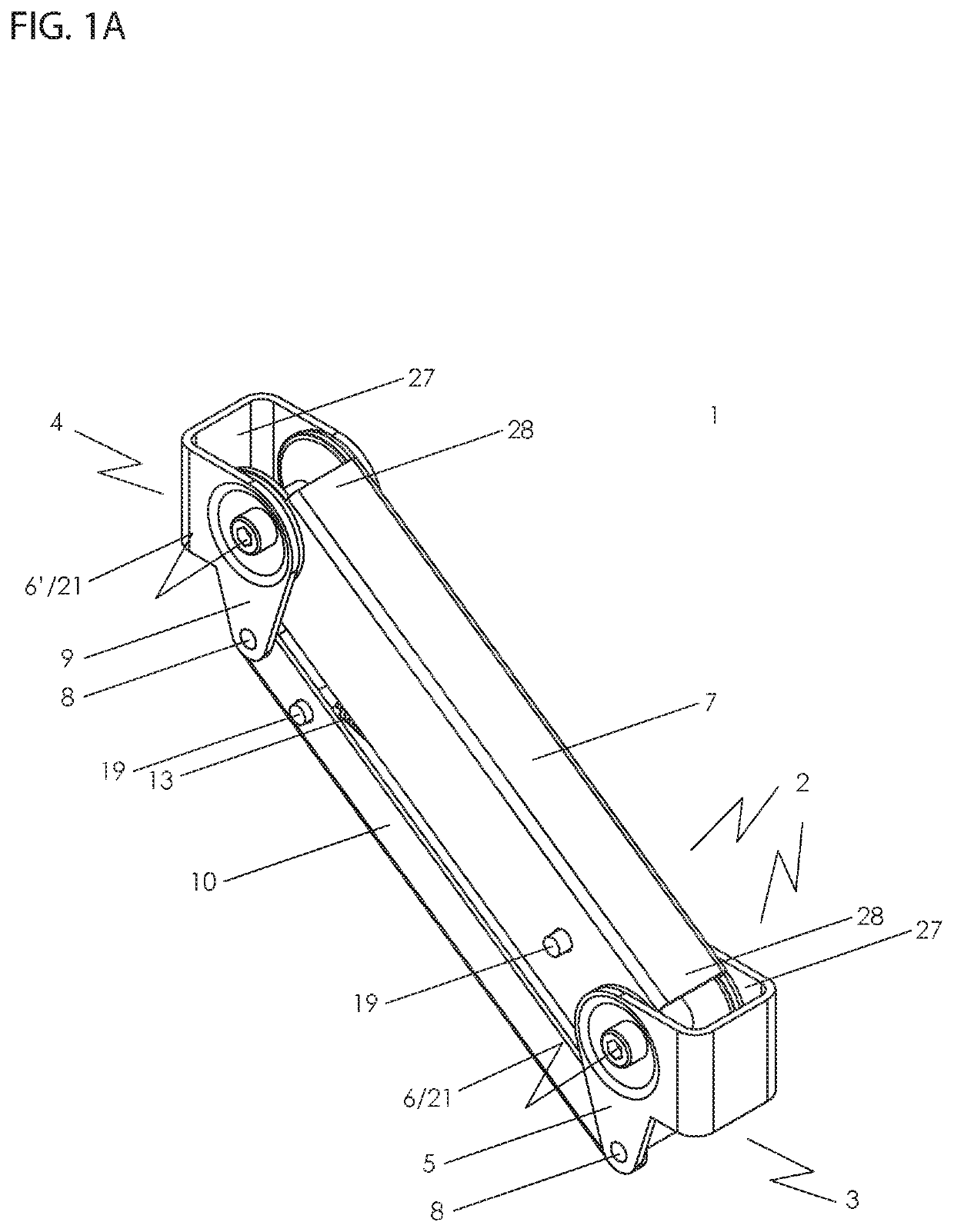
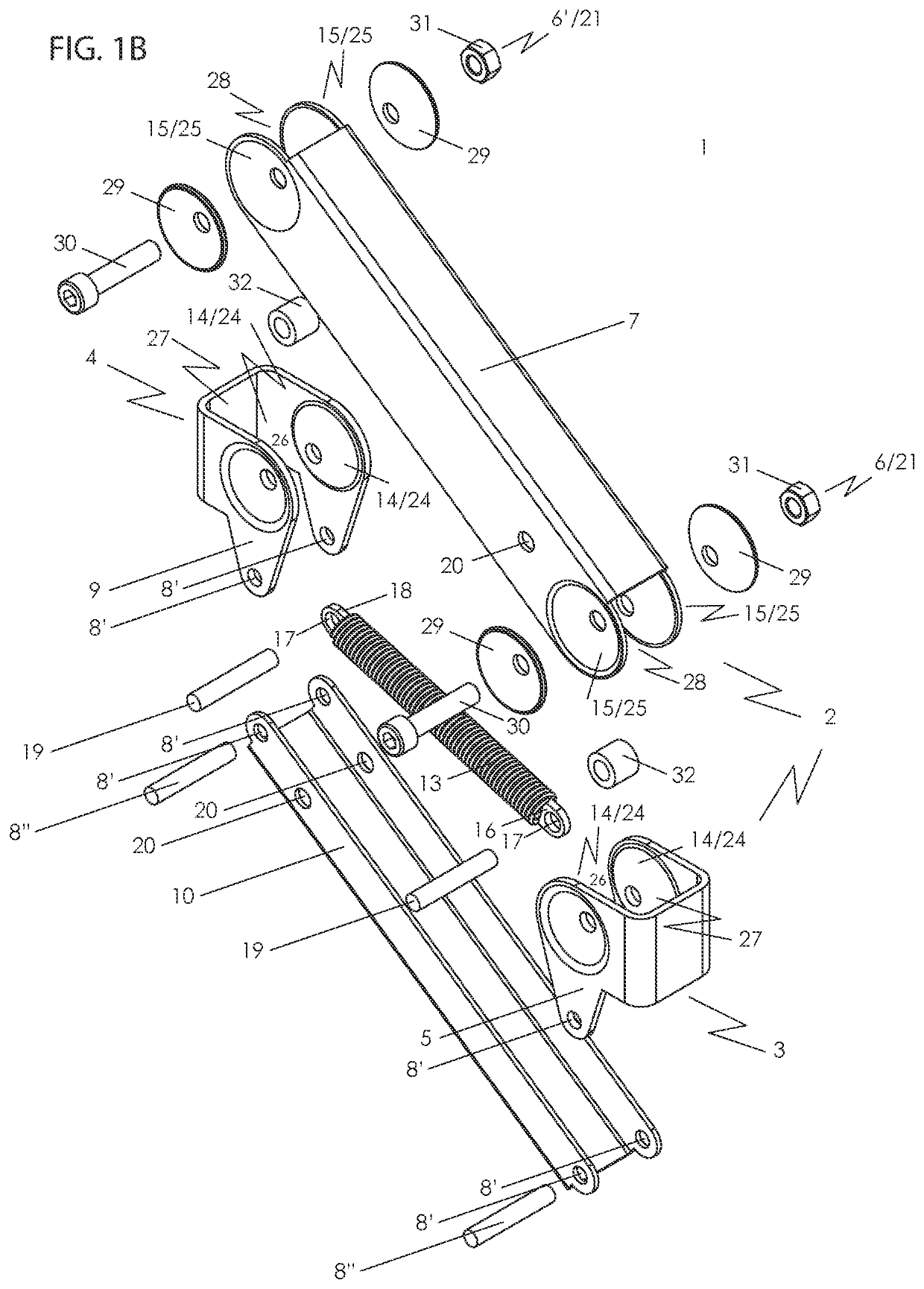
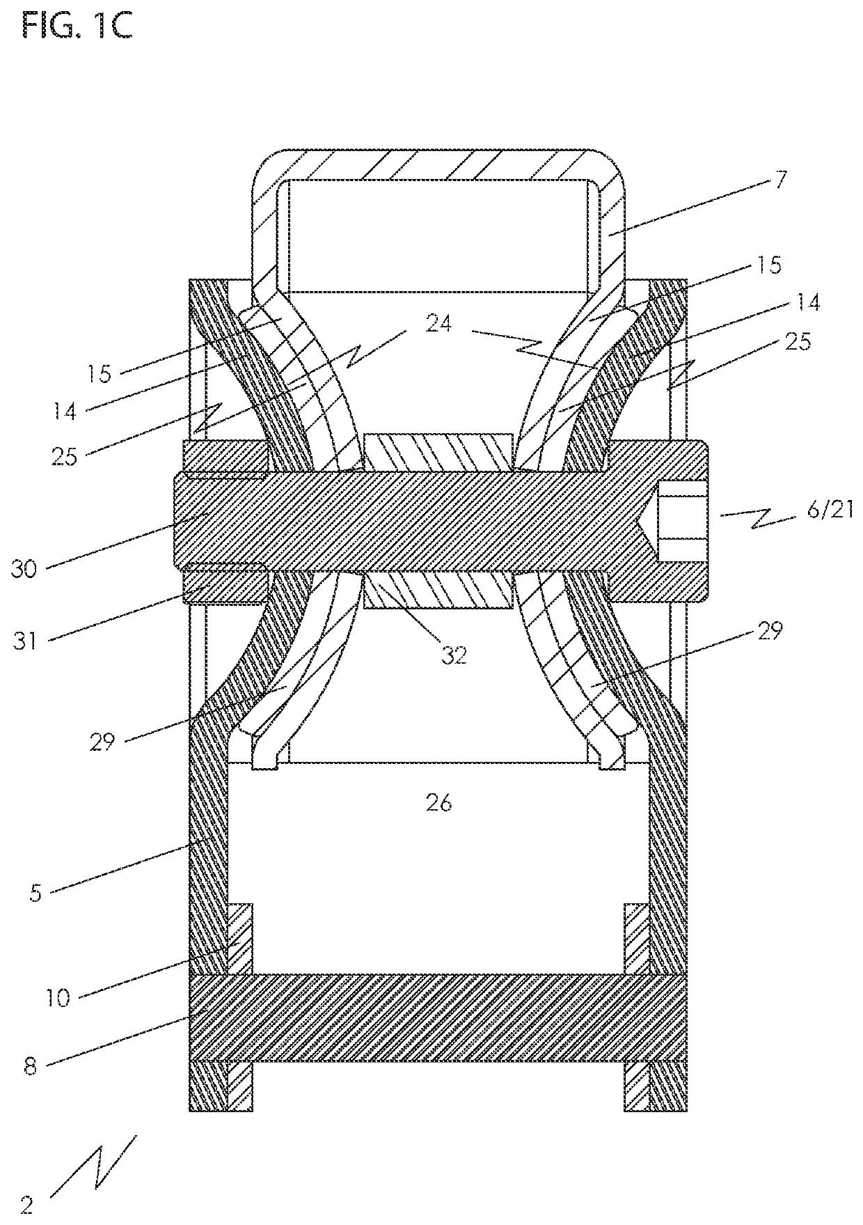
[0031]FIGS. 1a-1c show a first embodiment of a balancing arm 1 in accordance with the invention. The balancing arm 1 comprises a folding arm 2 that extends between a first end 3 that is held in position, and a second end 4 on which a load is carried. Typically, the first end 3 may be held on a clamp on a desk, and the second end 4 may carry a VESA mount of a computer display monitor, so that the monitor may be adjusted in height relative to a desk.

[0032]A first folding arm portion 5 of the folding arm 2 extends from the first end 3 of the folding arm 2 and is pivotably connected via a friction hinge 6 to a second folding arm portion 7 of the folding arm 2. The second folding arm portion 7 extends to the second end 4 of the folding arm 2. The friction hinge 6 in the folding arm 2 allows angular adjustment of the first folding arm portion 5 of the folding arm 2 relative to the second folding arm portion 7 of the folding arm 2, and thus positional adjustment of the second end 4 of the ...


PUM


Abstract

A balancing arm, comprising a folding arm that extends between a first end that is held in position, and a second end on which a load is carried, a first folding arm portion that extends from the first end of the folding arm being pivotably connected via a hinge to a second folding arm portion that extends to the second end of the folding arm. The balancing arm further comprises a balancing force device that is arranged to act between the first and second ends of the folding arm across the friction hinge to balance the load carried on the second end of the folding arm. The friction hinge is embodied as a friction hinge with adjustable friction, and includes a head and a socket arranged to pivot relative to each other when the folding arm portions pivot.

Description

BACKGROUND1. Technical Field[0001]The invention relates to a balancing arm with a friction hinge. Balancing arms are well known, and have traditionally been used in counterbalanced desk lamps. A particularly useful application of a balancing arm is in a monitor arm stand.2. Description of Related Art[0002]A balancing arm, also known as a floating arm or a counterbalanced arm, is a folding arm that is adjustable in position and that is constructed so that the load on the folding arm is counteracted by a balancing force device included in the folding arm, regardless of the position of the folding arm. The folding arm can be moved into a desired position, and the balancing force device is used to maintain that desired position until the folding arm is moved again.[0003]A balancing arm typically comprises a folding arm that extends between a first end that is held in position, and a second end on which a load is carried, e.g. a computer display monitor. A first folding arm portion exten...

Claims


Application Information

Patent Timeline
Patent Type & Authority Patents(United States)
IPC IPC(8): E04G3/00F16M13/02F16C11/06
CPCF16M13/022F16C11/06F16M2200/044F16M11/24F16M11/2092F16M2200/063F16M2200/022
Inventor VLAAR, ERIK JACOBUS
Owner VLAAR INNOVATIONS
Why Eureka
Try Eureka