

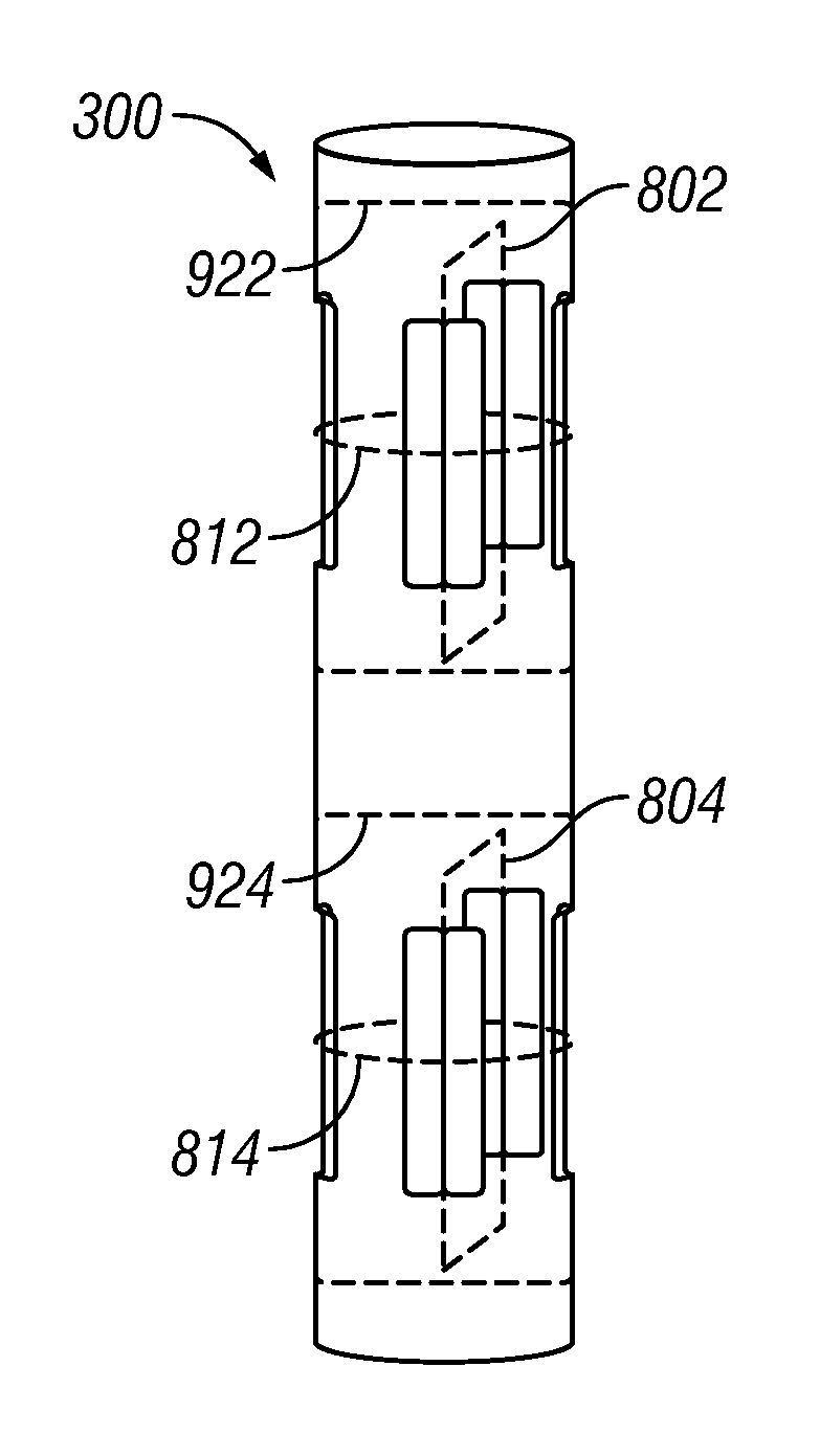
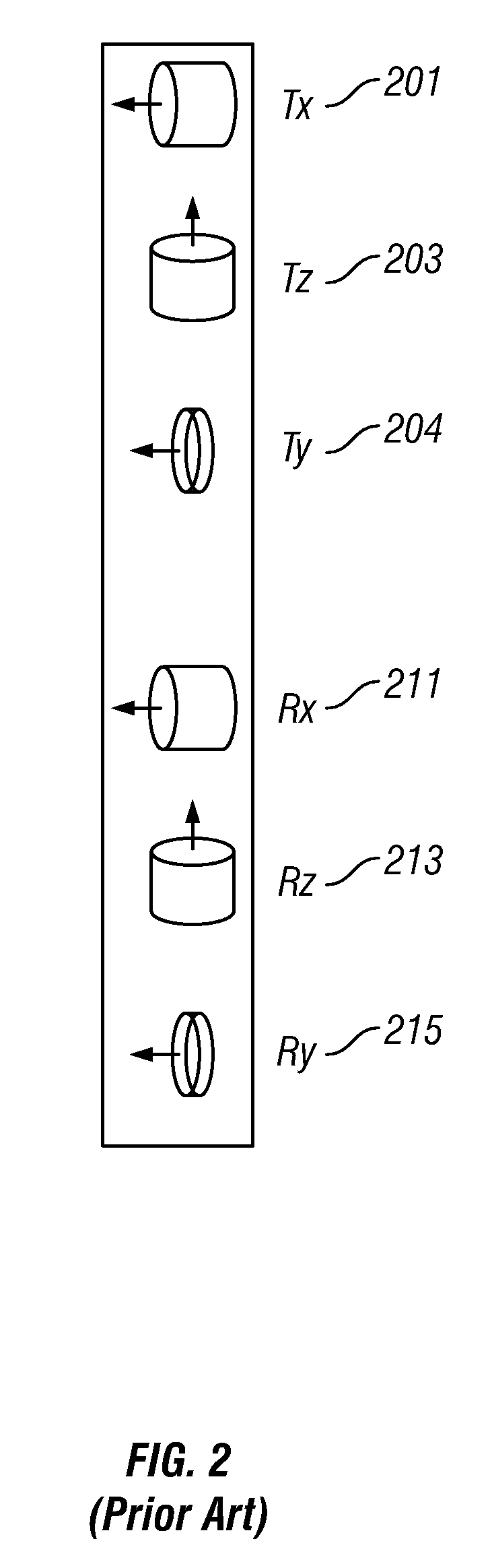
Multi-component resistivity logging tool with multiple antennas using common antenna grooves
a resistivity logging and multi-component technology, applied in the field of multi-component resistivity logging tools with multiple antennas using common antennas, can solve the problems of large number of grooves and more difficult to place multiple antennas compactly on the tool string, and achieve high magnetic permeability, and high magnetic permeability material
- Summary
- Abstract
- Description
- Claims
- Application Information
AI Technical Summary
Problems solved by technology
Method used
Image

Examples
Embodiment Construction
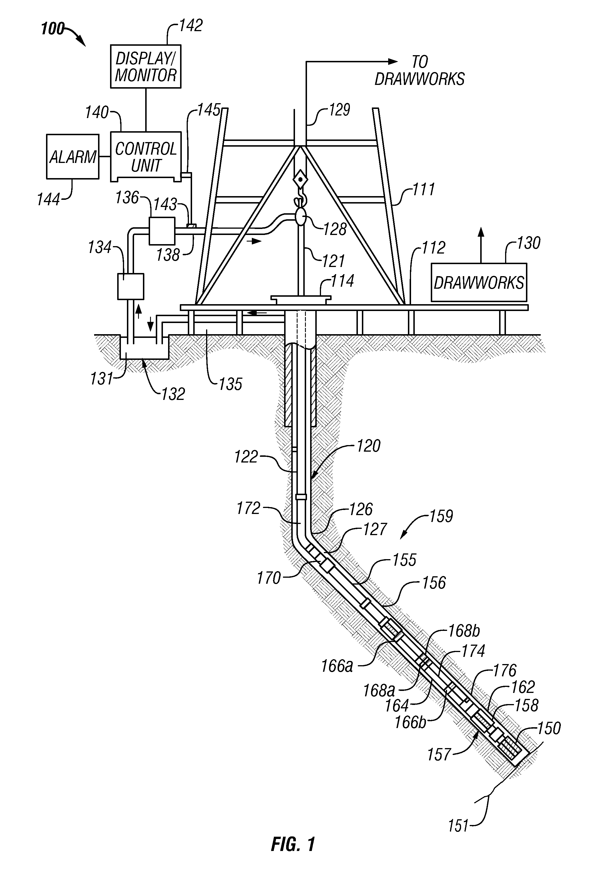
[0030]FIG. 1 shows a schematic diagram of a drilling system 110 having a downhole assembly containing an acoustic sensor system and the surface devices according to one embodiment of present disclosure. As shown, the system 110 includes a conventional derrick 111 erected on a derrick floor 112 which supports a rotary table 114 that is rotated by a prime mover (not shown) at a desired rotational speed. A drill string 120 that includes a drill pipe section 122 extends downward from the rotary table 114 into a borehole 126. A drill bit 150 attached to the drill string downhole end disintegrates the geological formations when it is rotated. The drill string 120 is coupled to a drawworks 130 via a kelly joint 121, swivel 118 and line 129 through a system of pulleys 127. During the drilling operations, the drawworks 130 is operated to control the weight on bit and the rate of penetration of the drill string 120 into the borehole 126. The operation of the drawworks is well known in the art...
PUM
 Abstract
Description
Claims
Application Information