Supercharge Your Innovation With Domain-Expert AI Agents!

Fuel injector for a gas turbine engine combustion chamber

a fuel injector and combustion chamber technology, which is applied in the direction of machines/engines, combustion types, lighting and heating apparatus, etc., can solve the problem of not allowing for optimum combustion at all running speeds

Active Publication Date: 2010-12-14
SN DETUDE & DE CONSTR DE MOTEURS DAVIATION S N E C M A
View PDF11 Cites 3 Cited by
  • Summary
  • Abstract
  • Description
  • Claims
  • Application Information

AI Technical Summary

Benefits of technology

[0007]It is an object of the present invention to produce a fuel injector that allows staged combustion, that is to say that makes it possible to create one combustion zone in the idling phase and a main combustion zone, that meets the ever tightening standards concerning the emission of pollutants.
[0009]Whereas in the prior art the main air flow surrounds the combustion zone for running at idle speed and to a certain extent masks it, the solution of the invention makes it possible to create a combustion zone for running at idle speed which is not masked by the main air flow, the lateral flame propagation thereby being improved.

Problems solved by technology

This system does not allow for optimum combustion at all running speeds, because the conditions vary between engine idling speed and full throttle.

Method used


Image

  • Fuel injector for a gas turbine engine combustion chamber
  • Fuel injector for a gas turbine engine combustion chamber
  • Fuel injector for a gas turbine engine combustion chamber

Examples


Embodiment Construction

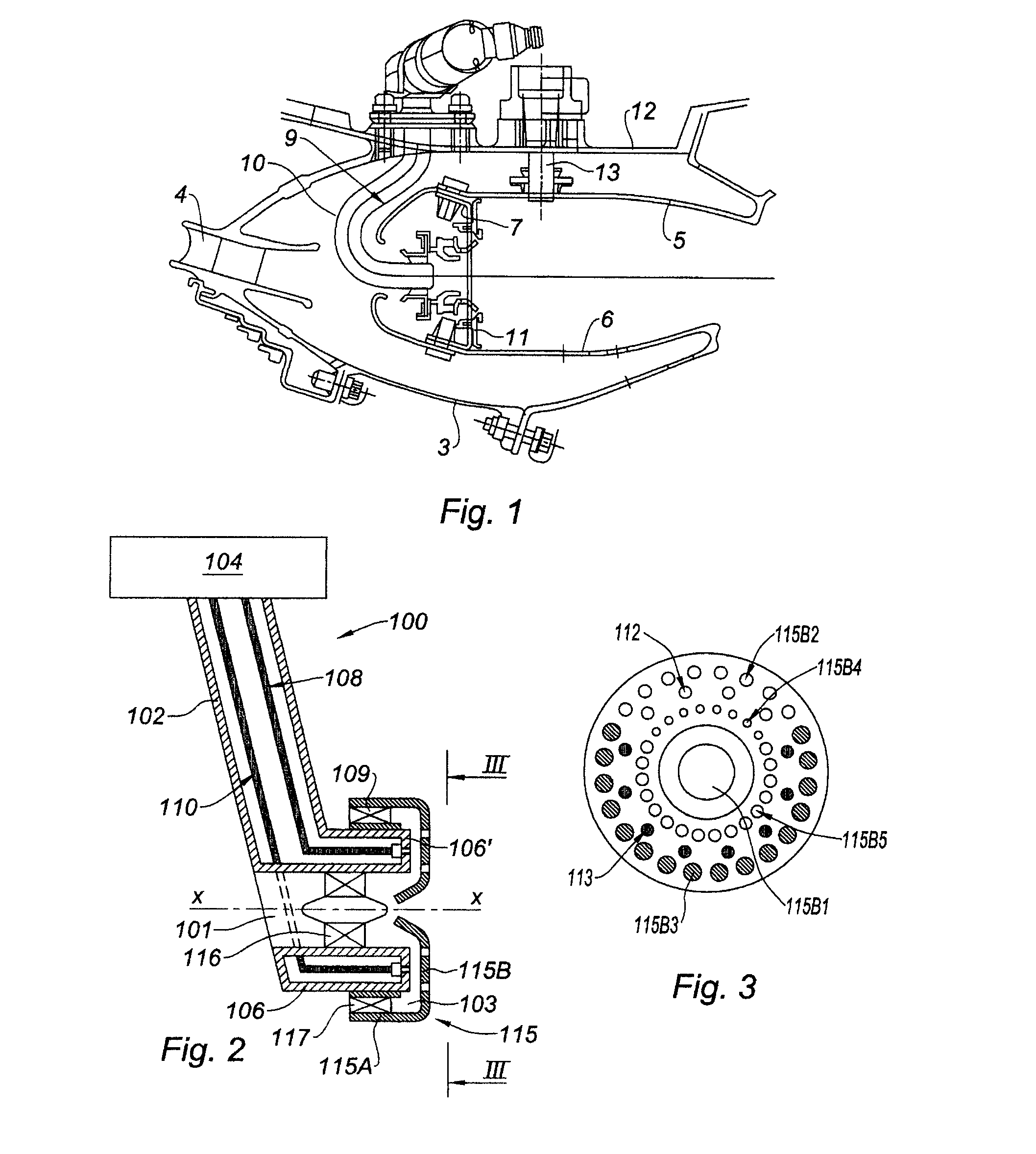
[0022]The gas turbine engine combustion chamber 1 to which the injector of the invention may be applied is annular and mounted, as is known, between an outer case 2 and an inner case 3, which is cylindrical, along the engine axis. The cases 2 and 3 thus form an annular space that is open upstream, with respect to the gas flow, onto a diffuser 4 communicating with the final stage of the compressor, not depicted. The chamber is open downstream onto the first turbine stage, not depicted, that receives the gases heated in the chamber. The chamber is made up of an outer wall 5 and of an inner wall 6 in the form of shell rings formed together and supported by appropriate flanges on the elements of the case. Upstream, the chamber is delimited by a chamber end wall 7 which is transverse with respect to the gas flow in the chamber. This wall 7 is provided with circular axial openings into which the fuel and the primary combustion air emerge. Some of this air and the fuel are mixed in mixers ...


PUM


Abstract

A fuel injector for a gas turbine engine combustion chamber is disclosed. The fuel injector includes a first fuel supply line for running at idle speed, a second, main, fuel supply line for running at speeds up to full throttle, and first and second injection orifices with which the two fuel supply lines respectively communicate. The injection orifices are arranged in a ring and the first orifices occupy a sector of the ring.

Description

BACKGROUND OF THE INVENTION AND DESCRIPTION OF THE PRIOR ART[0001]The present invention relates to the field of gas turbine engines and is aimed in particular at means for injecting fuel into the combustion chambers of such engines.[0002]The combustion chamber of a gas turbine engine is functionally positioned between the compression section from which it receives the air after it has been compressed, and the turbine section that it supplies with hot gases. It is generally contained inside an annular enclosure delimited by a radially outer casing and a radially inner wall protecting the drive shafts. According to one embodiment of the prior art, the chamber in which combustion takes place is itself defined between two coaxial shell rings, one of them an inner shell ring and the other an outer shell ring, spaced apart from the abovementioned two walls by appropriate flanges or supports. The upstream chamber end, at the compressor end, is provided with an upstream cowling by means of ...

Claims


Application Information

Patent Timeline
Patent Type & Authority Patents(United States)
IPC IPC(8): F02C1/00
CPCF02C7/22F23R3/30F23R3/346F23D2900/11001F23D2900/11101
Inventor BAINVILLE, FRANCOIS RENE DANIELSANDELIS, DENIS JEAN MAURICETOUCHAUD, STEPHANE HENRI GUY
Owner SN DETUDE & DE CONSTR DE MOTEURS DAVIATION S N E C M A
Features
  • R&D
  • Intellectual Property
  • Life Sciences
  • Materials
  • Tech Scout
  • Unparalleled Data Quality
  • Higher Quality Content
  • 60% Fewer Hallucinations
Learn More