Three-part laminated pliable hand-moldable surface construction

a pliable, three-part technology, applied in the direction of closure using stoppers, liquid handling, nuclear elements, etc., can solve the problems of difficult to easily change the shape of the device, difficult to easily change the size of conventional oil draining devices, and difficult to purchase smaller and larger devices

Active Publication Date: 2010-12-14
LOHMEIER KEVIN F
View PDF9 Cites 7 Cited by
  • Summary
  • Abstract
  • Description
  • Claims
  • Application Information

AI Technical Summary

Benefits of technology

[0015]A surface construction, in accordance with the invention, comprises three parts: a center lead sheet covered by two sheets of laminated rubber. The main structural part of the surface construction is the sheet of lead that is pliable and hand-moldable of an appropriate size and shape. Adhered onto and covering both sides of the lead sheet are the sheets of rubber. The lead sheet provides the functional and structural foundation for the pliable, hand-moldable and shape-retention characteristics of the surface construction. The rubber sheets protect the lead sheet, and provide insulative, caustic, abrasion resistance and other protection characteristics with regard to both personnel handling the surface construction and the material or environment with which the surface construction is used. The composition of the rubber sheets is therefore provided as appropriate for functional and protection purposes in consideration of the material or environment to which the surface construction is exposed. For instance neoprene rubber is suitable to withstand exposure to certain chemicals, while nitrile rubber is generally preferred for handling petroleum-based liquids. Those skilled in the material arts will recognize that other rubber compositions will be most suitable to achieve certain desired characteristics, such as abrasion resistance, softness or hardness, durability to repeated flexing and compression, and other material characteristics.
[0035]Another objective of the invention is to provide a protective cover that can be easily decontaminated and reused multiple times.

Problems solved by technology

Significant problems can result from such devices being fixed in configuration.
It is not possible to easily change the shape of the device to provide a custom way to drain oil or direct the flow of fluid to accommodate custom needs such as dictated by unusual engine configurations and drain port locations.
It is also not possible to easily change the sizes of conventional oil draining devices, other than perhaps cutting off the length of a rubber tube.
Consequently, smaller and larger size devices must often be purchased to accommodate special size limitations of particular needs.
Another disadvantage of conventional oil draining devices is that they often do not provide large surface flow area which would be convenient to collect and channel large volumes of fluid.
Another problem with conventional oil draining devices is that they are typically bulky, and cannot be conveniently stored in a compact form or limited space location.
Thus, while conventional oil draining devices may be suitable for the particular purpose to which they are intended to address, they are not easily adaptable for unusual circumstances, and their use can present difficulties in certain instances.
As one example, use of conventional oil draining devices can be a continuing problem in draining oil from certain aircraft engines where the oil filter is located in a difficult to reach place, and draining the oil during removal of the filter can result in discharge of oil on other parts of the engine, requiring additional, but otherwise unnecessary, cleanup and maintenance procedures
Removal of the top results in exposed sharp edges where the post frame supporting the top is cut through by the rescue personnel.
Additional exposed sharp edges may also be present on the vehicle as a result of the accident.
The main problem with conventional extrication pads is that they do not mold in-place over exposed jagged edges, for example, the cut-through “A, B, C” top support posts of a vehicle from which a person needs to be removed.
Conventional extrication pads placed over such jagged edges can be inadvertently shifted out of position, as when brushed by a person walking or moving by the post, exposing part of a jagged edge, or knocked entirely off of the end of the post.
Another problem with conventional extrication pads is that they can not be easily decontaminated of bodily fluids such as with bleach and water, and therefore cannot typically or easily be reused.
Another problem with conventional extrication pads is that they often cannot be conveniently stored on a rescue vehicle.
Thus, conventional extrication pads are only marginally suitable for protecting rescue personnel from dangers presented by jagged edges such as formed by cutting off the top, or a door or even other parts of vehicles.

Method used


Image

  • Three-part laminated pliable hand-moldable surface construction
  • Three-part laminated pliable hand-moldable surface construction
  • Three-part laminated pliable hand-moldable surface construction

Examples


Embodiment Construction

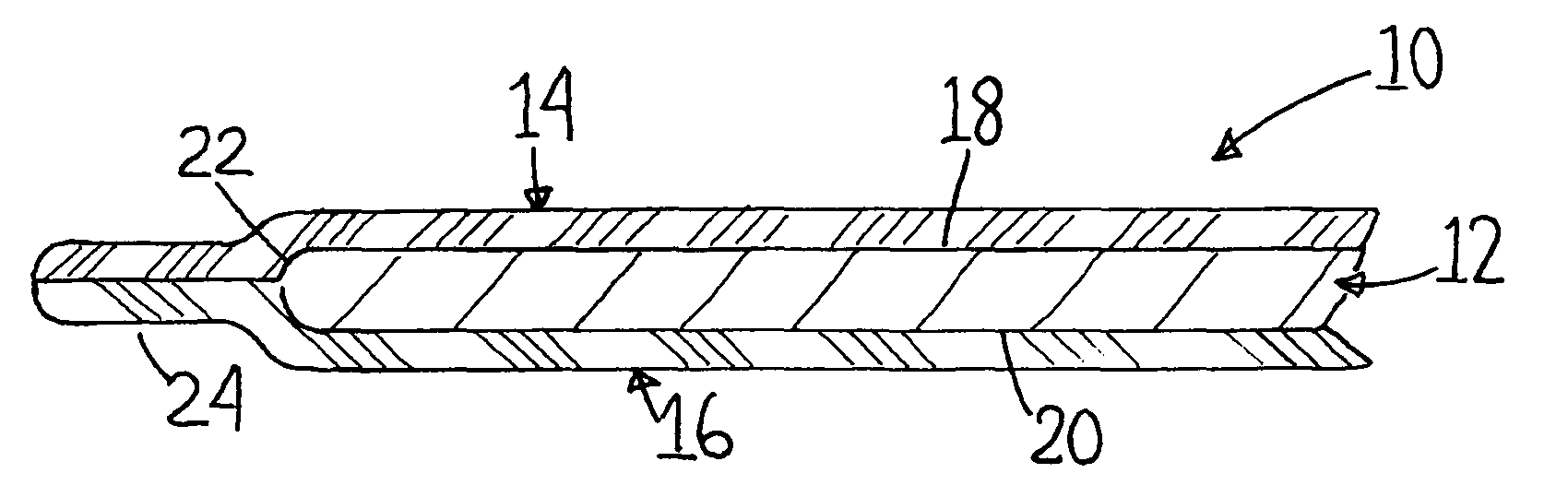
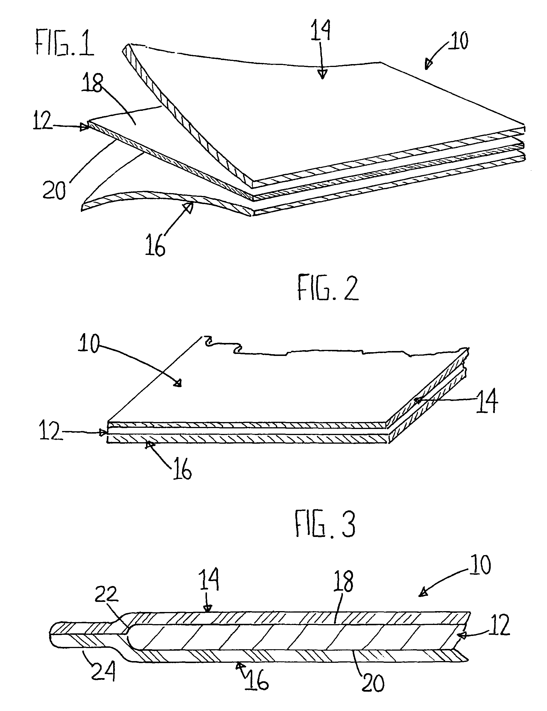
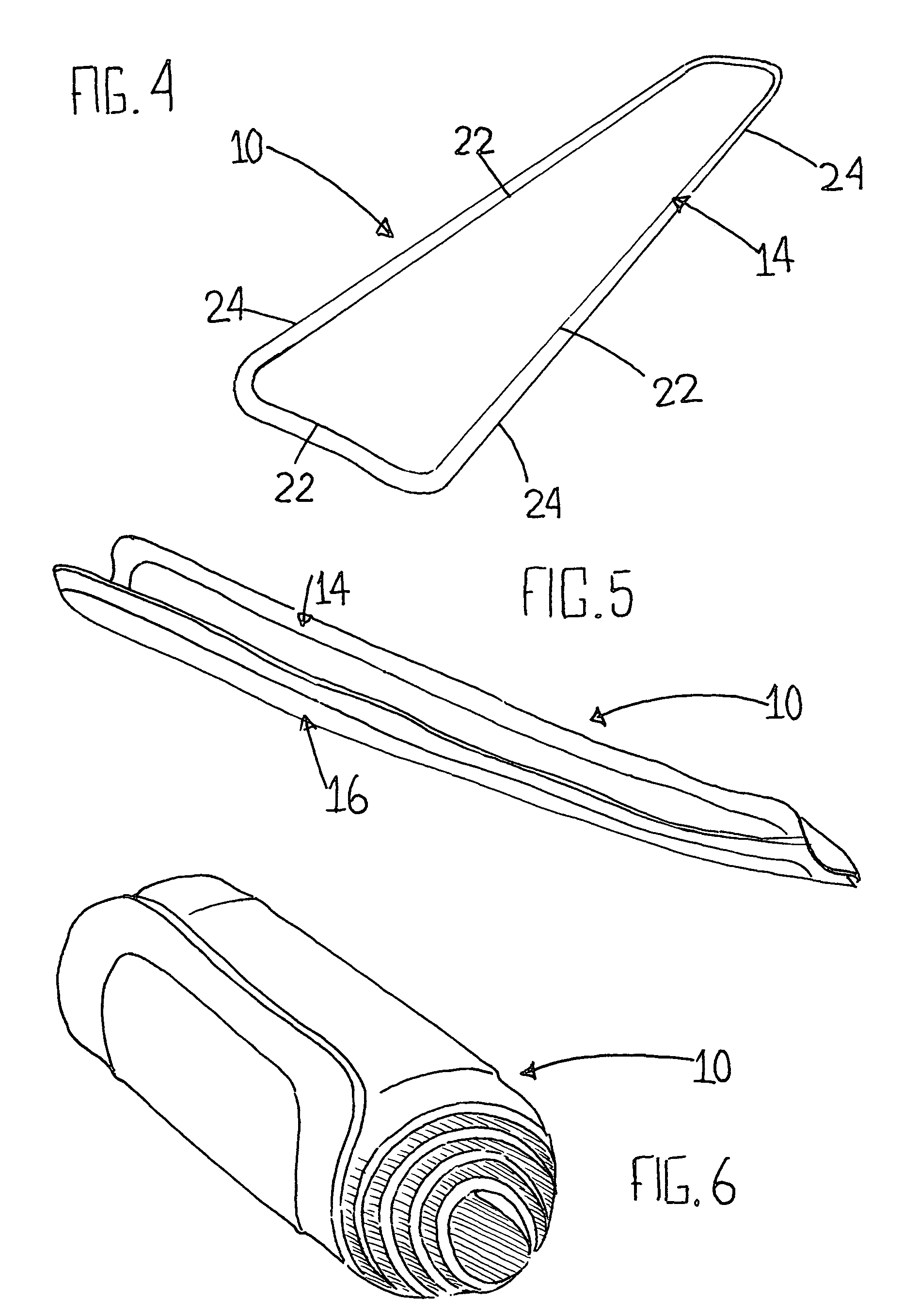
[0056]Turning now descriptively to the drawings, in which similar reference characters denote similar elements throughout the several views, there is shown a three-part laminated pliable hand-moldable surface construction 10 (see FIG. 4 for an overall perspective) which comprises three main layers. The center layer of the surface construction 10 is a pliable hand-moldable sheet of lead designated as item 12 (see FIGS. 1-3), both sides of which are covered with an appropriate pliable material layer 14, 16 such as thin rubber. This configuration establishes a three part laminated hand-moldable and pliable surface construction 10 which can be manually shaped to a desired configuration, optionally cut to a desired size, and is adaptable for many purposes, including but not limited to channeling the flow of liquid from one location to another, and forming a protective cover over exposed jagged edges.

[0057]More particularly, the middle layer of the surface construction 10 is a sheet of le...


PUM

PropertyMeasurementUnit
thicknessaaaaaaaaaa
sizeaaaaaaaaaa
shape-retentionaaaaaaaaaa

Abstract

A three-part laminated surface construction can be shaped and molded by hand and will retain that shape until the particular need is met, such as controlling the flow of liquids and resins, or establishing a protective cover. The surface construction includes a center sheet of lead with rubber layers secured over the lead. The perimeter of the rubber layers are secured together. The lead sheet can be provided with outer flaps, one soft rubber side and the other rubber side abrasion-resistant for folding around and protection from sharp objects.

Description

CROSS-REFERENCES TO RELATED APPLICATIONS[0001]This application claims priority to U.S. Provisional Patent Application Ser. No. 60 / 673,008, filed Apr. 20, 2005, U.S. Provisional Patent Application Ser. No. 60 / 692,523, filed Jun. 21, 2005, and U.S. Provisional Patent Application Ser. No. 60 / 722,614, filed Sep. 30, 2005.INCORPORATION-BY-REFERENCE OF MATERIAL SUBMITTED ON A COMPACT DISC[0002]Not Applicable.STATEMENT REGARDING FEDERALLY SPONSORED RESEARCH OR DEVELOPMENT[0003]Not Applicable.BACKGROUND OF THE INVENTION[0004]1. Field of Invention[0005]The present invention relates generally to a pliable hand-moldable surface construction.[0006]More specifically, the invention relates to a three-part laminated pliable hand-moldable surface construction which, while suitable for other uses, is particularly useful for channeling the flow of liquids and resins such as for draining engine oil from hard to reach locations, and for covering sharp edges such as formed by cutting off parts of a vehi...

Claims


Application Information

Patent Timeline
Patent Type & Authority Patents(United States)
IPC IPC(8): B32B15/06
CPCB32B15/08B60R13/043Y10T428/1386Y10T428/24Y10T428/1359B32B2307/554B32B25/10B32B2581/00B32B1/08B32B15/14B32B3/04B32B15/06
Inventor LOHMEIER, KEVIN F.
Owner LOHMEIER KEVIN F
Why Eureka
Try Eureka